
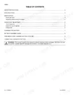
Printed under Link-Belt Book No. 9-44510LX, this 610-page Link-Belt 290 LX shop manual PDF is the factory text for the 290 LX crawler excavator, organized in nine sections from general data and standard torques through the upperstructure. Upperstructure hydraulics fill well over a third of the book: removal and teardown of the main and pilot pumps, main control valve, swing motor, hydraulic swivel and attachment cylinders, plus the pressure settings you verify before condemning a component. Large-format hydraulic and electrical schematics trace each circuit, while undercarriage and drive train chapters cover track removal, idler service, and travel and swing reduction gear rebuilds. Refill the hydraulic reservoir with 31.7 gallons (63.4 for the full circuit) and torque the travel motor and reduction gear assembly to 664 to 774 lb-ft. Out on site, nobody else is there to ask. Bookmarked and text-searchable, it lets you confirm which assembly you're replacing before ordering, so the part is right the first time.
What's Inside This Link-Belt 290 LX Manual
| System | Pages | Key Topics |
|---|---|---|
| General Information | 1-38 | Safety Precautions, Standard Torque Data |
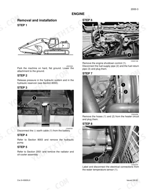
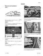
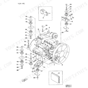
| Engine | 39-50 | Removal and Installation of the Engine, Radiator and Oil-Cooler, Engine Specifications, Disassembly and Assembly of the Engine |
| Fuel System | 51-56 | Fuel Tank, Fuel Engine System |
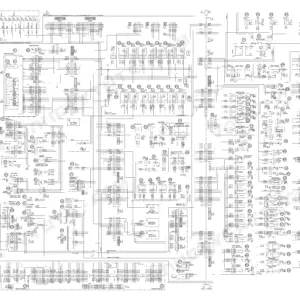
| Electrical System | 57-160 | Electrical and Electronic Troubleshooting, General Location of Components, Monitor Displays |
| Undercarriage | 161-214 | Removal and Installation of Tracks, Upper and Lower Rollers, Sprocket Removal and Installation, Idler Wheel and Tension Shock Absorber |
| Drive Train | 215-252 | Travel Motor Reduction Gear Assembly, Swing Reduction Gear Removal, Swing Reduction Gear Disassembly, Travel Reduction Gear Assembly |
| Undercarriage Hydraulics | 253-288 | Pressure Release and Decontamination, Hydraulic Pressure Setting |
| Upperstructure Hydraulics | 289-527 | Depressurising and Decontaminating the Hydraulic System, Specifications, Troubleshooting, Checks and Hydraulic Pressure Settings, Hydraulic Reservoir Removal and Installation |
| Upperstructure | 528-610 | Turntable and Counterweight, Boom, Dipper and Bucket, Seat and Seat Belt, Cab and Cab Equipment, Air Conditioning Troubleshooting, Air Conditioning Unit Disassembly and Assembly |
Quick Reference Specifications
| Specification | Value | Page |
|---|---|---|
| Engine oil capacity | 6.3 gallons | p. 21 |
| Engine cooling circuit capacity | 7.6 gallons | p. 21 |
| Hydraulic fluid reservoir capacity | 31.7 gallons | p. 21 |
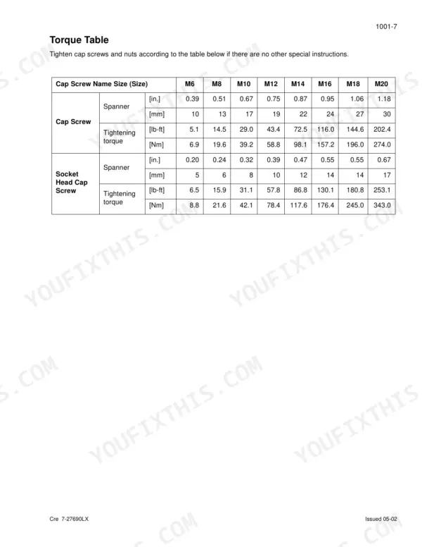
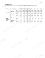
| Travel motor and reduction gear assembly torque | 664-774 lb-ft | p. 35 |
| Sprocket torque | 384-448 lb-ft | p. 35 |
| Engine Idle Speed | 1000 rpm | p. 21 |
| Engine Max Speed | 2200 rpm | p. 21 |
| Engine SAE Net Horsepower | 177.5 HP | p. 21 |
| Engine Max Torque | 499 lb-ft at 1800 rpm | p. 21 |
| Fuel Reservoir Capacity | 89.8 gallons | p. 21 |
| Main Circuit Relief Pressure (Standard) | 4975 ± 43 psi | p. 22 |
| Main Circuit Relief Pressure (Power-up) | 5410 ± 72 psi | p. 22 |
Link-Belt 290 LX Common Problems This Manual Covers
Link-Belt 290 LX hydraulic pressure inspection shows main circuit relief pressure out of spec
Check main circuit relief pressure at the standard setting against 4975 ± 43 psi, then at power-up against 5410 ± 72 psi, both listed on page 22. Release trapped hydraulic pressure before you break any fitting to install the gauge. Adjust the relief following the Hydraulic Pressure Setting and Inspection procedure, then recheck the gauge.
Manual Section: Hydraulic Pressure Setting and Inspection p. 22Pilot system relief pressure reading out of spec during hydraulic pressure check
Measure pilot circuit relief pressure and compare the reading against 566 ± 14 psi, listed on page 22. Check it first, before chasing main relief or attachment secondary reliefs. Adjust the pilot relief following the Hydraulic Pressure Setting and Inspection procedure, then recheck the reading before moving on.
Manual Section: Hydraulic Pressure Setting and Inspection p. 22Machine pulls to one side with travel drift when driven in a straight line
Test travel drift following the Hydraulic Pressure Setting and Inspection procedure before you pull anything apart. If the travel circuit checks out, inspect the travel motor and brake valve following the Travel Hydraulic Motor inspection steps. When you reinstall the travel motor and reduction gear assembly, torque the bolts to the 664-774 lb-ft listed on page 35.
Manual Section: Undercarriage Hydraulics p. 253Swing motor brake failing to release, or failing to hold the upperstructure in position
Check swing brake release following the Hydraulic Pressure Setting and Inspection procedure. If release checks out, remove the swing motor and inspect it following the Swing Hydraulic Motor Disassembly and Assembly steps. Verify brake torque meets the 694 lb ft minimum on page 23, then torque the swing motor and reduction gear assembly to 577-673 lb-ft.
Manual Section: Swing Hydraulic Motor Disassembly and Assembly p. 23Monitor display showing an active diagnostic code, with the cause not obvious from the cab
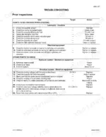
Record the code exactly as the monitor shows it, then look it up in the Electrical and Electronic Troubleshooting section starting on page 57. Work the listed checks in order, using the troubleshooting procedures and the wiring diagram to trace the circuit. Test each connector in that circuit before replacing any part.
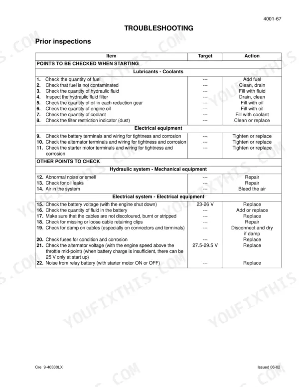
Manual Section: Electrical and Electronic Troubleshooting p. 57Battery charge circuit fault with the battery not charging while the engine runs
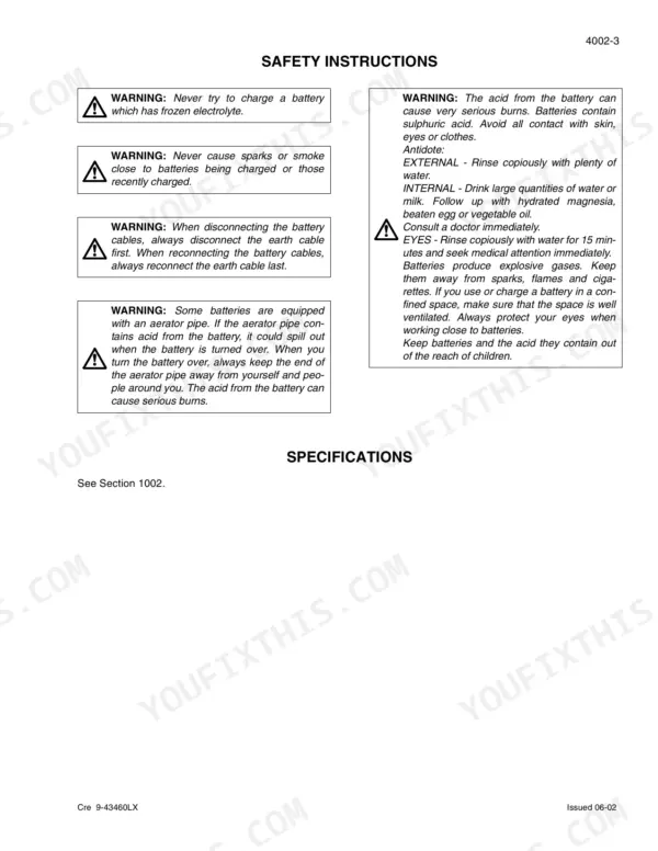
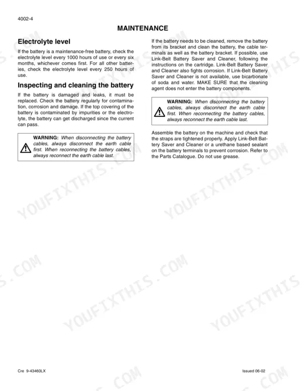
Check the battery charge circuit step by step in the Electrical and Electronic Troubleshooting section that starts on page 57, tracing the wiring on the diagram. Verify the battery mounting is tight and torque it to the 15-21 lb-ft listed on page 35 so vibration cannot work it loose.
Manual Section: Electrical and Electronic Troubleshooting p. 57Frequently Asked Questions
How do I clear a fault code on a Link-Belt 290 LX?
To erase diagnostic data, press the work mode switch for a minimum of 10 seconds while in the diagnostic mode. The audible warning device will sound to confirm the data has been erased. p. 110
What is the torque specification for the swing motor retaining screws on a Link-Belt 290 LX?
The swing motor retaining screws should be tightened to a torque of 450 ± 30 lb-ft. p. 354
What is the hydraulic pressure specification for the main circuit relief (standard) on a Link-Belt 290 LX?
The main circuit relief (standard) pressure is set to 4975 ± 43 psi. p. 22
What is the engine oil capacity for the Link-Belt 290 LX?
The engine oil capacity for the Link-Belt 290 LX is 6.3 gallons. p. 21
What is the torque specification for the engine retaining screws on the 290 LX excavator?
The engine retaining screws should be tightened to a torque of 214 ± 18 lb-ft. p. 43
What do I get after purchasing this Link-Belt 290 LX manual?
A single searchable PDF file of 610 pages, downloadable right after payment. Nothing ships, nothing waits in the mail.
Can I print a copy of this Link-Belt 290 LX Shop Manual for the shop?
Yes. Printing works from any reader and any printer, for your own shop use.


Reviews
There are no reviews yet.