
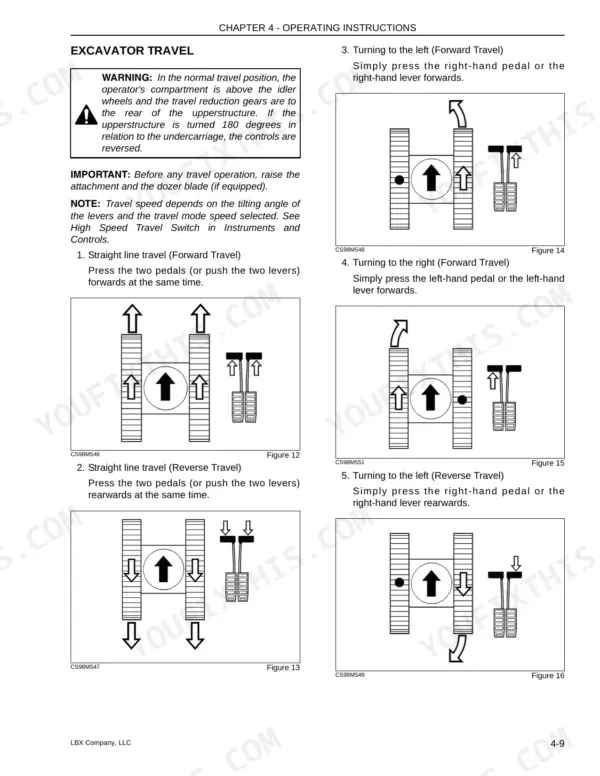
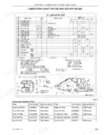
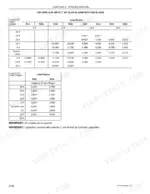
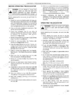
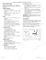
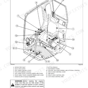
Hydraulic system service, from releasing trapped pressure to changing the return and pilot filters, is the toughest work in this 162-page Link-Belt 135 operator manual PDF (OEM ID 1207) for the 135 Spin Ace Tier III hydraulic crawler excavator, but it is only the start. Lubrication, filters, and fluids fill the largest share of the book, with grease charts for machines with and without the dozer blade, a capacities table, and swing and travel reduction gear checks. Your operator gets the instrument panel, both control arms, the C and D pattern selector, transport and slope procedures, and how to lower the attachment after a machine failure. Swap the fuel pre-filter every 250 hours and the main fuel filter at 500, and set rubber track tension to 8.7-9.4 in. (220-240 mm). One missing figure can park a crew for the morning. Bookmarked and text-searchable, this copy stays yours for as long as you run the 135.
What's Inside This Link-Belt 135 Spin Ace Tier III Operator Manual
| System | Pages | Key Topics |
|---|---|---|
| General Information | 1-12 | To the Owner, Excavator Components, Identification Numbers |
| Safety, Decals, and Hand Signals | 13-34 | Safety Rules, Safety Area, Utility Safety, Operator Precautions, Decals, Hand Signals |
| Instruments and Controls | 35-64 | Cab Door, Steps and Access Handles, Position of the Operator’s Compartment Controls and Accessories, Right-Hand Control Arm, Instrument Panel |
| Operating Instructions | 65-86 | Before Operating the Excavator, Operating the Excavator, Run-In Period, Starting the Engine, Bringing the Excavator Up to Operating Temperature, Engine Operation |
| Lubrication, Filters, and Fluids | 87-120 | Servicing Instructions, Daily Inspections, Hourmeter, Lubrication Chart for 135 Spin Ace with Blade, Lubrication Chart for 135 Spin Ace Without Blade, Fluids and Lubricants |
| Maintenance and Adjustments | 121-136 | Tracks (Checking the Condition of Rubber Tracks, Replacing the Rubber Tracks), Track Rollers and Idler Wheels, Radiator and Oil Cooler, Fan and Alternator Drive Belt |
| Electrical | 137-144 | Fuses, Battery, Connecting One or Two Booster Batteries, Alternator, Starter Motor, Replacing a Bulb, Working Lights |
| Specifications | 145-160 | Engine, Electrical Systems, Hydraulic System, Undercarriage, Capacity of Systems and Components, Weights, Boom, Arms |
Quick Reference Specifications
| Specification | Value | Page |
|---|---|---|
| Track Tension Value (Rubber tracks) | 8.7-9.4 in. (220-240 mm) | p. 125 |
| Track Tension Value (Steel tracks) | 9.4-10.5 in. (240-269 mm) | p. 125 |
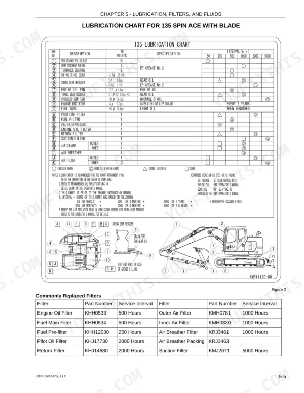
| Pilot Oil Filter Service Interval | 2000 Hours | p. 91 |
| Return Filter Service Interval | 2000 Hours | p. 91 |
| Fuel Main Filter Service Interval | 500 Hours | p. 91 |
| Fuel Pre-filter Service Interval | 250 Hours | p. 91 |
| Travel reduction gear torque | 267-312 Nm (197-230 lbf-ft) | p. 136 |
| Drive sprocket torque | 267-312 Nm (197-230 lbf-ft) | p. 136 |
| Engine Oil Capacity | 4.54 gal (17.2 liters) | p. 95 |
| Fuel Tank Capacity | 43.59 gal (165 liters) | p. 95 |
| Hydraulic System Total Capacity | 34.34 gal (130 liters) | p. 95 |
| Travel Reduction Gear Oil Capacity | 0.55 gal (2.1 liters) | p. 95 |
Link-Belt 135 Spin Ace Tier III Common Problems This Manual Covers
Link-Belt 135 Spin Ace track sagging loose between the idler wheel and drive sprocket
Measure track tension following the check on page 125. Rubber tracks should read 8.7-9.4 in. (220-240 mm); steel tracks should read 9.4-10.5 in. (240-269 mm). Adjust tension back into range, then check grouser height against the 5 mm wear limit on page 126 before you order a replacement track.
Manual Section: Track Maintenance and Troubleshooting p. 125Engine running hot partway through a shift and overheating indicator coming on at the instrument panel
Clean the radiator and oil cooler, then inspect the fan and alternator drive belt in the Maintenance and Adjustments section starting on page 121. If the engine still runs hot, drain, rinse and refill the cooling system following the cooling procedure, then recheck the overheating indicator once the machine is back at operating temperature.
Manual Section: Maintenance and Adjustments p. 121Water collecting in the fuel filter or air trapped in the fuel system after a filter change
Drain water from the fuel filter, then replace the fuel filters at the intervals listed in the maintenance schedule on page 91. Bleed air from the fuel system after every filter change, and verify the engine starts and idles smoothly before you put it back to work.
Manual Section: Fuel System TroubleshootingAir trapped in hydraulic components after replacing the pilot filter or return filter
Check that hydraulic system pressure is released before you open a line, then bleed air from the affected components following the hydraulic procedure. Replace the pilot filter at 2000 hours per page 109, matching the 8 micron pilot and 6 micron return filter ratings on page 147. Verify oil level; total system capacity is 34.34 gal (130 liters).
Manual Section: Hydraulic System Troubleshooting p. 109Hydraulic cylinder rod coming out wet with an oil film after a shift of work
Clean the cylinder rod, cycle the function, then inspect the rod appearance against the cylinder leak test in the Maintenance and Adjustments section starting on page 121. If the rod condition points to a leak, tag the machine and report it before the next shift rather than running it and hoping.
Manual Section: Maintenance and Adjustments p. 121Engine cranks slowly or will not crank with a weak battery or blown fuse
Check the fuses and battery condition in the Electrical section starting on page 137. If the battery is down, connect one or two booster batteries following the jump starting procedure. Once it starts, inspect the alternator and starter motor per the same section so the crew is not standing around tomorrow morning.
Manual Section: Electrical p. 137Frequently Asked Questions
What are the replacement specs for the hydraulic return and pilot filters on the Link-Belt 135 Spin Ace Tier III?
The pilot oil filter (part number KHJ17730) and the return filter (part number KHJ14680) should be replaced every 2000 hours. If the excavator is new or a major component has been overhauled, these filters must be replaced after the first 50 hours of operation. p. 91
What are the fuel filter and water separator element replacement specs for the Link-Belt 135 Spin Ace Tier III?
The fuel main filter (part number KHH0534) should be replaced every 500 hours, and the fuel pre-filter (part number KHH12030) should be replaced every 250 hours. p. 91
What is the required tightening torque for the track shoe bolts on the Link-Belt 135 Spin Ace Tier III?
The tightening torque for the track shoe bolts must be between 267 to 312 Nm (196 to 230 ft lb). p. 125
What is the hydraulic reservoir capacity and total hydraulic system capacity of the Link-Belt 135 Spin Ace Tier III?
The hydraulic reservoir has a capacity of 21.40 gallons (81 liters), while the total hydraulic system capacity is 34.34 gallons (130 liters). p. 95
What is the correct tension slack for the fan and alternator drive belt?
The tension slack for the fan and alternator drive belt should be between 0.39 and 0.59 inches (10 to 15 mm) when 20 lbs of pressure is applied to the center of the belt. p. 130
How is this Link-Belt 135 Operator Manual delivered?
A single searchable PDF file of 162 pages, downloadable right after payment. Nothing ships, nothing waits in the mail.
Can I print this Link-Belt 135 manual?
Yes. Print the pages or sections you need for your own shop use. Any standard printer works.

Reviews
There are no reviews yet.