
If your fleet runs a Manitou MLT 635 130 PS D ST4 S1, MLT 733 105 D ST4 S1, MLT 737 130 PS D ST4 S1, or the 733 Tract variant, this 300-page repair manual PDF (OEM ID 647603EN) is written for your telehandler. Electrical work takes up nearly half the book: wiring diagrams map the network architecture and ECU inputs and outputs, and DTC error code tables decode what the controllers report. Hydraulic schematics trace oil through the accumulator block, steering unit, counterbalance valve and RS 14 distributor, while engine chapters cover ECU, DEF injection and DOC removal plus Compact+ and Powershift gearbox service. Put a manometer on the transmission and look for 15 to 18 bar at the pump (T3) and 5 to 8 bar at the converter (T1). A transmission diagnosis stalls on one missing pressure figure. Bookmarks land you on the right chapter, and text search finds any fault code in seconds.
What's Inside This Manitou MLT 635 130 PS, 733 105, 737 130 PS ST4 S1 Repair Manual
| System | Pages | Key Topics |
|---|---|---|
| General Instructions and Safety Notice | 12-16 | Foreword, Servicing Position, Explanation of Symbols, Servicing Rules |
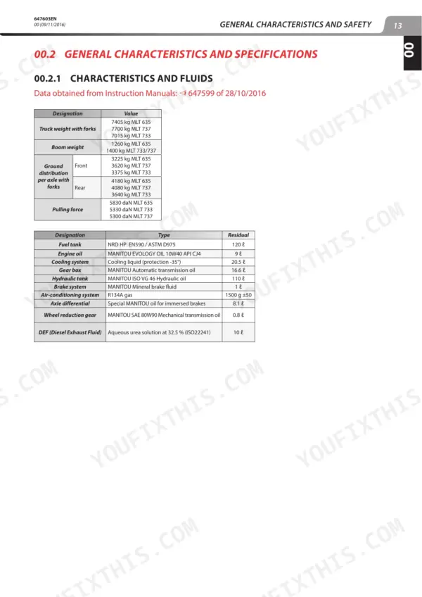
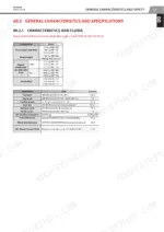
| General Characteristics and Specifications | 17-19 | Characteristics and Fluids, Dimensions (Mlt: 635 / Mlt 737, 733 / Mlt 733 Tract) |
| General Location | 20 | Name and Identification Plate |
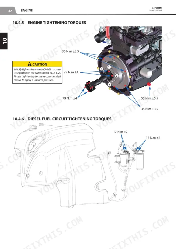
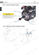
| Engine Characteristics and Specification | 21-45 | Injection Cycle, Bosch CP4.1 High Pressure Pump, Engine Schematic Diagram, Lubrication Circuit, Cooling System, Fuel Circuit |
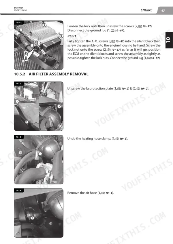
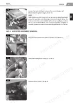
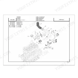
| Engine Removal and Refit | 46-72 | Engine ECU Removal, Air Filter Assembly, Starter Removal, DOC Exhaust Pipe, DEF Injection System, Cooler Removal |
| Transmission Schematic Diagrams and Components | 73-86 | Compact+ Manual Gear Box, Powershift Gear Box, Transmission ECU, Gear Change Modes, Drive Train, Shaft and Clutch |
| Transmission Control, Adjustment, and Removal | 87-100 | Transmission Tightening Torques, Gear Box Removal, Angle Drive Assembly, Manometer Sets |
| Axle and Brake Systems | 101-108 | Axle Control, Brake Pedal Adjustment, Brake Bleeding Procedure, Brake Master Cylinder |
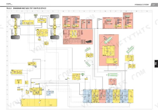
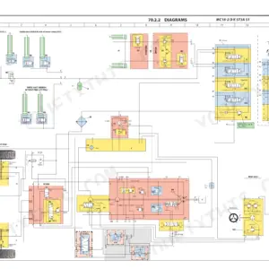
| Hydraulic System | 109-148 | Boom Component Removal, Hydraulic Characteristics, Accumulator Block, Steering Unit, Counterbalance Valve, Distributor RS 14 |
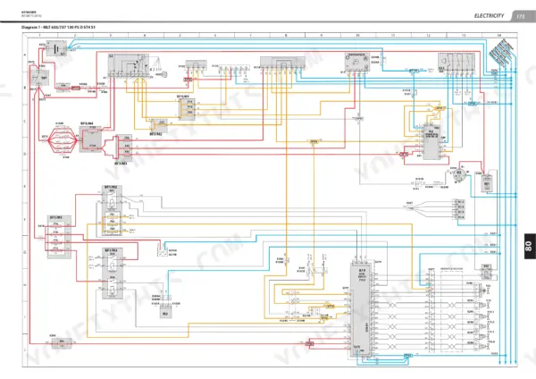
| Electricity and Electrical Troubleshooting | 149-156 | Electrical Network Architecture |
| ECU Inputs / Outputs | 157-226 | Fuses and Relays, Accelerator Potentiometer, Fuel Level Sensor, ECU Inputs and Outputs |
| Battery Removal | 227-229 | Dashboard Display Screen |
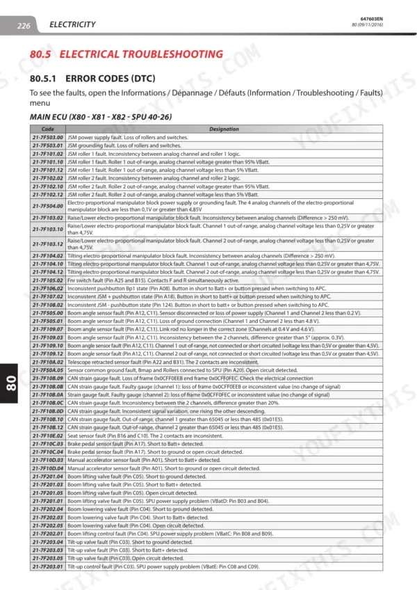
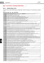
| Error Codes (DTC) | 230-265 | PS+ Transmission ECU, CVT Transmission ECU, Engine ECU |
| Driver's Cab | 266-286 | Cab Removal, Driver's Seat Removal |
| Frame, Body, and Options | 287-300 | Engine Bonnet Removal, Air-Conditioning Operation, Condenser Components, Air-Conditioning Belt Removal |
Quick Reference Specifications
| Specification | Value | Page |
|---|---|---|
| Pressure relief valve opening pressure | 9 bar | p. 29 |
| Fuel rail maximum service pressure | 1600 bar | p. 27 |
| PRV (Pressure Relief Valve) opening pressure | 1700 bar | p. 26 |
| Supply voltage | 12 V | p. 157 |
| Pump (T3) pressure | 15 to 18 bar | p. 88 |
| Converter (T1) pressure | 5 to 8 bar | p. 88 |
| Engine Power Rating | 90 kW | p. 25 |
| Engine Maximum Unladen Speed | 2360 rpm | p. 25 |
| Air-Conditioning Refrigerant Load | 1500 g ± 50 | p. 17 |
Manitou MLT 635 130 PS, 733 105, 737 130 PS ST4 S1 Common Problems This Manual Covers
Manitou MLT 635/733/737 engine power reduction in degraded mode level 1 or 2 with excessive back pressure
Check which degraded mode the engine is in, level 1 or level 2, before chasing parts. If the ECU flags excessive back pressure, park the machine and run a stationary mode regeneration, letting it finish without interruption. Then confirm power returns. If the engine has shut down, work through the DEF regeneration checks before putting it under load.
Manual Section: Engine Control and Adjustment (DEF Regeneration)Engine fan drive not completing its reversal cycle or stuck running in degraded mode
Check whether the fan control has dropped into degraded mode and whether fan speed adjustment still responds. Verify the reversal cycle actually runs and the fan changes direction for the full cycle. Then pull any stored error codes and work through the troubleshooting actions in the electrical tables starting before replacing parts.
Manual Section: Fan Control (Fan Drive Reversal)PS+ transmission ECU storing error codes with pump, converter or lubrication pressure out of spec
Read the PS+ transmission ECU codes from the table, then fit the manometer set and check pressures following page 88. Pump (T3) should read 15 to 18 bar, converter (T1) 5 to 8 bar and lubrication (T5) 0.75 to 1.25 bar. Confirm all three readings before you condemn the ECU.
Manual Section: PS+ Transmission ECU Troubleshooting (Error Codes)Main ECU (SPU 40-26) showing error codes on a hydraulic solenoid circuit
Check the code in the main ECU table starting and follow the listed action. Verify the 12 V supply at the connector per page 157, then unplug the coil and measure its resistance against the 5.42 Ω nominal value on page 137. Rated current is 2.3 A; a coil reading open or shorted gets replaced.
Manual Section: Electrical Troubleshooting (Error Codes)Engine ECU (EDC17CV52) error codes with fuel rail pressure suspect at the Bosch CP4.1 pump
Check the code against the engine ECU troubleshooting tables and carry out the listed action before touching the pump. Verify rail pressure stays within the 1600 bar maximum service pressure on page 27, and remember the rail safety valve opens at approx. 1700 bar (page 26). Keep clear of the high pressure lines with the engine running.
Manual Section: Engine ECU Troubleshooting (Error Codes)Cab air conditioning with abnormal pressure readings, abnormal noise or an unpleasant smell
Check the refrigerant load first: the system is specified at 1500 g ±50 on page 17, and a wrong charge throws both pressures off. Inspect the air conditioning belt and condenser components for the source of any noise, then work through the pressure, noise and smell tables in the air conditioning troubleshooting section before replacing parts.
Manual Section: Air-Conditioning TroubleshootingFrequently Asked Questions
What is the procedure for bleeding the hydraulic brake system on a Manitou MLT?
To bleed the brakes, connect a hydraulic bleeder to the expansion tank. Then, turn the bleed screws in order from the furthest to the nearest: first the rear right and rear left, then the front right and front left. p. 106
What is the capacity of the hydraulic tank on the Manitou MLT?
The average capacity of the hydraulic tank is 110 liters, with a total system capacity of 135 liters. p. 139
What is the tightening torque for the cab silent block on the Manitou MLT 635 130 PS, 733 105, 737 130 PS ST4 S1?
The tightening torque for the cab silent block is 290 N.m ± 10. p. 266
What is the correct engine oil capacity for the Manitou MLT?
The engine oil capacity is 9 liters, using MANITOU EVOLOGY OIL 10W40 API CJ4. p. 17
How quickly can I access this Manitou manual after buying?
You download the Repair Manual yourself: 300 pages, searchable PDF, available immediately. Keep a copy on every device you use.
Can I print pages of this Manitou MLT 635 130 PS D ST4 S1 manual for my own shop?
Yes. It prints from any PDF reader, so run off the pages you need for your own repair work.
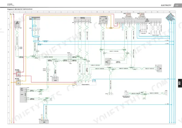
Does this Manitou MLT 635 130 PS D ST4 S1 manual have electrical diagrams?
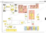
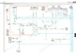
Yes, full electrical schematics are included with wire colors, connector locations, and circuit descriptions. You can see one on page 179.


Reviews
There are no reviews yet.