
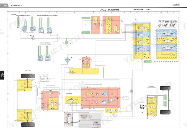
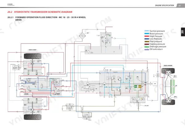
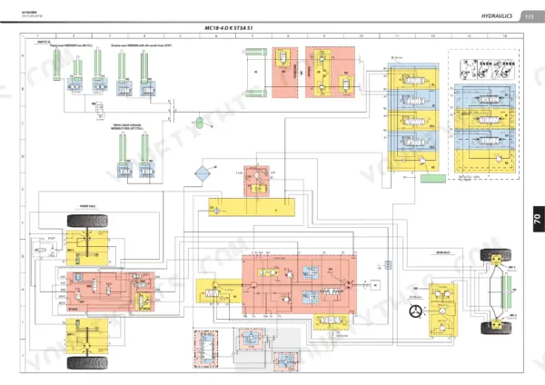
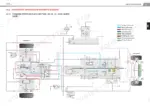
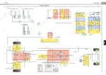
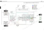
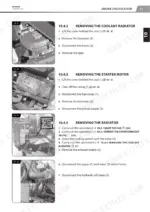
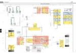
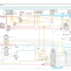
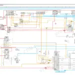
With an MC 25-4 parked in the bay and its hydrostatic pump due out before second shift, you want this 241-page Manitou repair manual PDF (OEM 647659EN) open on the bench; it covers nine lift trucks across the MC 18-2 to MC 30-4 and MSI 25 to MSI 35 diesel series. Hydraulics and electrics fill over half the book: wiring diagrams trace circuits to the ECU, and hydraulic schematics map oil from pump through valve block to the lift and tilt cylinders. Transmission work gets its own schematic, and the mast chapter covers rollers, wear plates, lift chains and removal. Fill the hydraulic tank to 66 L, and match the engine sump to the model: 6 L on an MC 18, 8.3 L on MC 25, MC 30 and MSI trucks. A guessed adjustment costs you a second teardown. Bookmarked and text-searchable, the PDF is bought once and stays yours for every hour this truck logs.
What's Inside This Manitou MC 18-2 to MSI 35 Repair Manual
| System | Pages | Key Topics |
|---|---|---|
| General Instructions and Safety Notice | 14-18 | Foreword, Servicing Position, Explanation of Symbols, Servicing Rules |
| General Characteristics and Specifications | 19-22 | Characteristics, Lubricants and Fuel, Dimensions |
| General Location | 23 | Location of Name and Identification Plate |
| Standard Tightening Torques | 24 | Screw/Nut Assembly, Hexagon Head Screws, Washer Coefficients, Tightening Torque Markings |
| Metric - Imperial Unit Conversion | 25 | Conversion Coefficients, Other Unit Conversions |
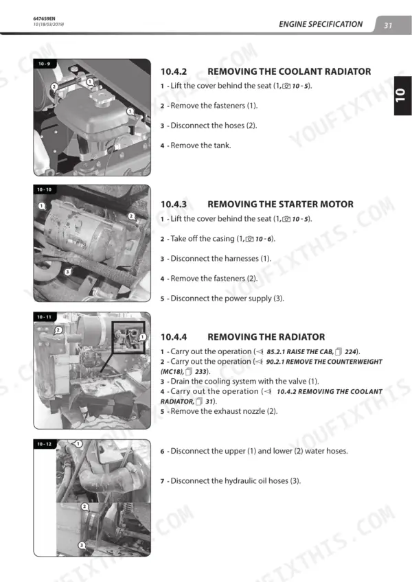
| Engine Specification and Controls | 27-54 | Engine Characteristics, Engine Removal, Alternator Removal, Starter Motor Removal, Belt Tension Adjustment, Vibration Measurement |
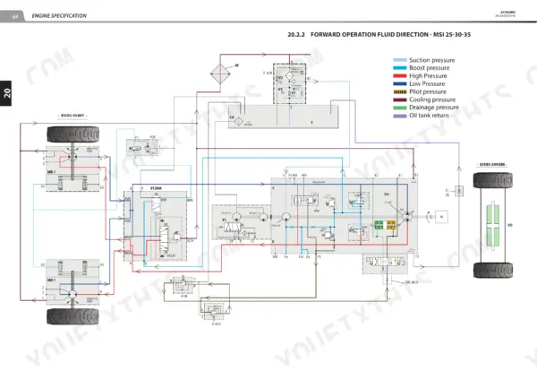
| Transmission Characteristics and Controls | 55-86 | Hydrostatic Pump, Hydraulic Wheel Motor, Transmission Schematic Diagram, Transmission Cut-Off, Disengagement Module, Transmission Removal |
| Axle Control and Adjustment | 87-92 | Tightening Torque, Rear Axle Mounting, Spindle Bearing Pre-Stressing, Turning Radii, Rear Axle Removal |
| Brake System | 93-96 | Brake Characteristics, Brake Diagrams, Inching-Brake Pedal Adjustment, Brake Contactor Adjustment |
| Mast Maintenance | 97-106 | Mast Characteristics, Roller Installation, Wear Plate Installation, Lifting Chain Assembly, Mast Removal |
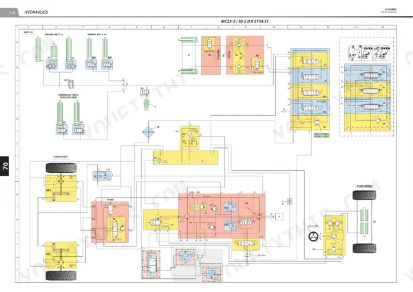
| Hydraulics | 107-126 | Hydraulic Valve Block, Hydraulic Pump Removal |
| Electricity | 127-137 | Electrical Data Sheets |
| Wiring Diagrams | 138-208 | Cab Installation |
| Electrical Location and Component Removal | 209-226 | ECU Removal |
| Driver's Cab | 227-241 | Cab Suspensions, Driver's Cab Removal |
Quick Reference Specifications
| Specification | Value | Page |
|---|---|---|
| MC 18 | ||
| Engine Oil Capacity (MC 18) | 6L | p. 19 |
| MC 25, MC 30, MSI 25, MSI 30, MSI 35 | ||
| Engine Oil Capacity (MC 25/30/MSI 25-30-35) | 8.3L | p. 19 |
| All Models | ||
| Hydraulic Tank Capacity | 66L | p. 19 |
| Brake System Fluid Capacity | 2L | p. 19 |
Manitou MC 18-2 to MSI 35 Common Problems This Manual Covers
Manitou MC 25-4 hydrostatic pump A4VG 56 DA not at mechanical zero, truck creeps in neutral
Set the A4VG 56 DA pump to mechanical 0 using the transmission adjustment procedure that begins on page 67. Fit a gauge, measure pump pressure with the engine running, then confirm the truck holds still in neutral. Check the HP relief valves while the gauge is still connected, before you button everything back up.
Manual Section: Transmission Controls and Adjustments p. 67HP relief valves out of calibration on hydrostatic transmission, weak travel and poor pulling under load
Measure pressure at the A4VG 56 DA pump following the procedure that starts on page 67. Then check and calibrate the HP relief valves to the settings listed there. Torque the connections to the values in that same section. If pressure still won't come up, pull the hydrostatic pump using the transmission removal steps.
Manual Section: Transmission Controls and Adjustments p. 67Inching-brake pedal height wrong and brake contactor not switching at the end of pedal travel
Adjust the inching-brake pedal height first, then set the end-of-travel stop using the brake section that opens on page 93. Adjust the brake contactor so it switches at the correct point in the pedal stroke. While you're there, check the brake fluid level. The system holds only 2L, so even a small loss shows up on the level.
Manual Section: Brake System p. 93Mast rollers and wear plates worn, mast has excessive play and lifting chain runs uneven
Inspect the mast rollers and wear plates and replace any worn parts following the installation steps in the mast maintenance section on page 97. Check the lifting chain assembly and reassemble it per the same section. If the mast has to come off, place it on the ground first, then remove it following the mast removal procedure.
Manual Section: Mast Maintenance p. 97Hydraulic pump seals leaking, oil weeping around the pump body and hydraulic tank level dropping
Remove the hydraulic pump following the hydraulic component removal procedure and replace the pump seals. Inspect the hydraulic tank while the pump is out. After refitting, refill with the oil specified in the lubricants table. The tank holds 66L according to page 19. Then run the truck and check again for leaks.
Manual Section: Hydraulic Component RemovalAlternator belt tension out of adjustment, drive belt slipping and squealing when engine is running
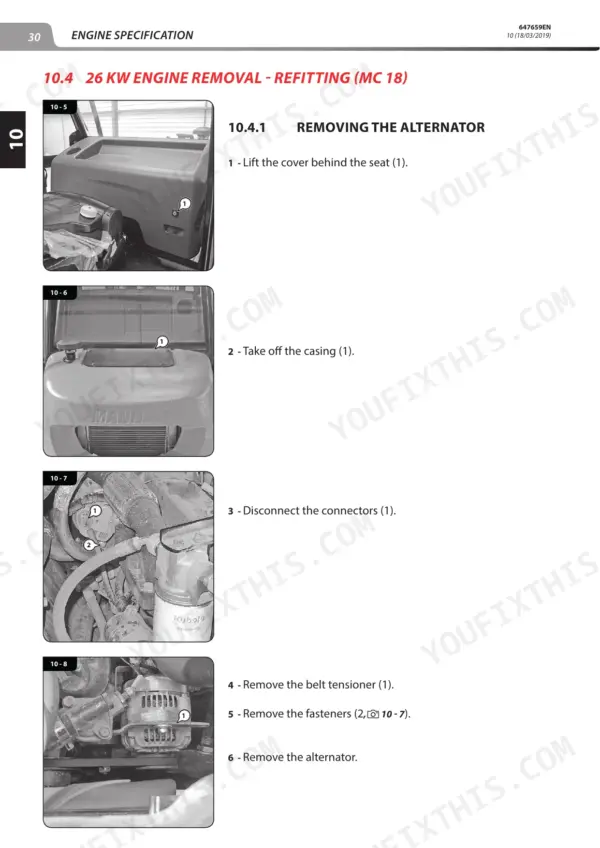
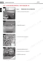
Check the belt tension and adjust it following the belt tension adjustment procedure in the engine section that begins on page 27. Inspect the belt for glazing or cracking and replace it if it's worn. If you suspect the alternator itself, remove it using the alternator removal steps in the same engine section.
Manual Section: Engine Specification and Controls p. 27Frequently Asked Questions
What is the tightening torque for M10 x 1.5 Grade 8.8 non-flanged screws on the Manitou MC 18-2 to MSI 35?
For M10 x 1.5 screws (Grade 8.8) without flanges, the standard tightening torque is 40 N.m (354 lb-in). p. 24
What is the correct belt tension for the engine alternator?
Check the belt tension between the crankshaft and alternator pulleys. Under normal pressure applied by the thumb (98 N), the belt movement A should be between 7 and 9 mm. p. 32
What is the tightening torque for the front wheel motor on the Manitou MC 18-2 to MSI 35 lift truck?
The tightening torque for the front wheel motor is 550 Nm ± 10%. p. 71
What is the engine oil capacity for the Manitou MC 18-2 to MSI 35 lift truck, specifically the MC 18 model?
The engine oil capacity for the MC 18 model is 6 liters (1.58 U.S. gallons). p. 19
How do I set the hydrostatic pump mechanical zero on a Manitou MC 18-2 to MSI 35 lift truck?
Connect a low-range (40 to 100 bar) manometer to each of the two HP pressure connectors. Ensure the handbrake is released, the machine is on blocks, the engine is idling, and the reversing shift is in neutral. Loosen the 'mechanical 0' adjustment screw locknut, then turn the screw to detect the variation in HP and adjust until the key is mid-way between the two marks. p. 73
What do I get after purchasing this Manitou MC 18-2 manual?
Instant PDF download. You get the full 241-page searchable Repair Manual immediately after payment. Open it on your laptop, tablet, or phone right in the shop.
Can I print this Manitou MC 18-2 manual?
Yes. Printing works from any reader and any printer, for your own shop use.


Reviews
There are no reviews yet.