
Manitou's MLT 840 and MLT 1040 repair manual PDF (647392EN, 647 pages) takes the telehandler apart system by system across six variants, ST3B and MLT-X ST3A builds alike, from engine removal to boom refit. Electricity is the biggest chapter in the book. Its wiring diagrams sit beside fault code tables and troubleshooting charts, so you can trace a no-crank complaint through to starter control relay K21. Hydraulic schematics anchor the second-largest section, together with removal and refit for the components they show, while the boom chapter adds its own schematic diagrams and specific tooling. Set relief valve 3 at 80 ± 5 bar, and bring the exhaust bracket bolts to 42 N.m ±3% when you refit them. Out in a muddy yard on your own, there's nobody to ask. Bookmarked by chapter with a live text layer, the PDF is bought once and stays on your drive for as long as you run this machine.
What's Inside This Manitou MLT 840, MLT 1040 Repair Manual
| System | Pages | Key Topics |
|---|---|---|
| General Instructions and Safety Notice | 4-25 | Preamble, Maintenance Position, Rules for Maintenance |
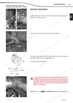
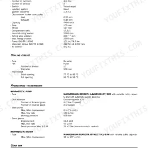
| Engine | 26-137 | Engine Characteristics and Specifications, Engine Components Location, Engine Control and Adjustment, Engine Removal, Engine Refit |
| Transmission | 138-183 | Transmission Characteristics and Specifications, Transmission Schematic Diagrams, Transmission Components Location, Transmission Control and Adjustment |
| Axle Assembly - Axle | 184-189 | Axle Control and Adjustment |
| Brake | 190-227 | Brake Characteristics and Specifications, Brake Control and Adjustment, Brake Removal, Brake Refit, Specific Brake Tooling |
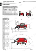
| Telescopic Boom | 228-313 | Boom Characteristics and Specifications, Boom Schematic Diagrams, Boom Components Location, Boom Control and Adjustment, Boom Removal, Boom Refit, Specific Boom Tooling |
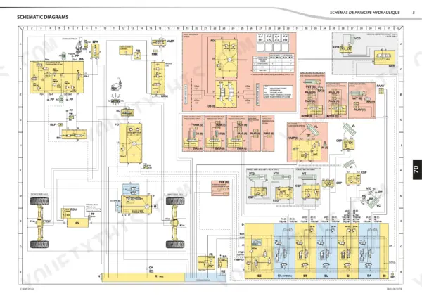
| Hydraulic | 314-429 | Hydraulic Characteristics and Specifications, Hydraulic Components Removal, Hydraulic Components Refit, Hydraulic Specific Tooling |
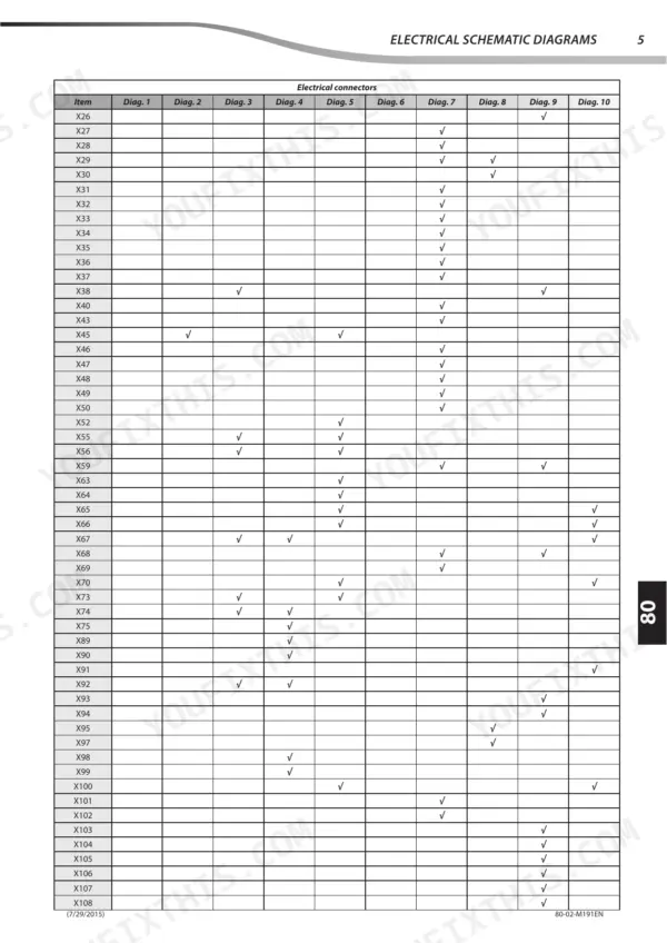
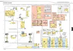
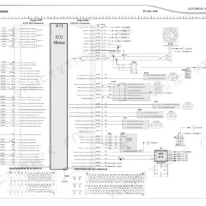
| Electricity | 430-607 | Electrical Characteristics and Specifications, Electrical Schematic Diagrams, Electrical Components Location, Electrical Control and Adjustment, Electrical Troubleshooting |
| Driver Cab | 608-625 | Driver Cab Components Location, Driver Cab Control and Adjustment, Driver Cab Removal, Driver Cab Refit |
| Frame - Body | 626-643 | Fuel Tank, Oil Tank, Stop Adjustment, Frame, Chassis |
| Options - Accessories | 644-647 | Frame Body Control and Adjustment |
Quick Reference Specifications
| Specification | Value | Page |
|---|---|---|
| All Models | ||
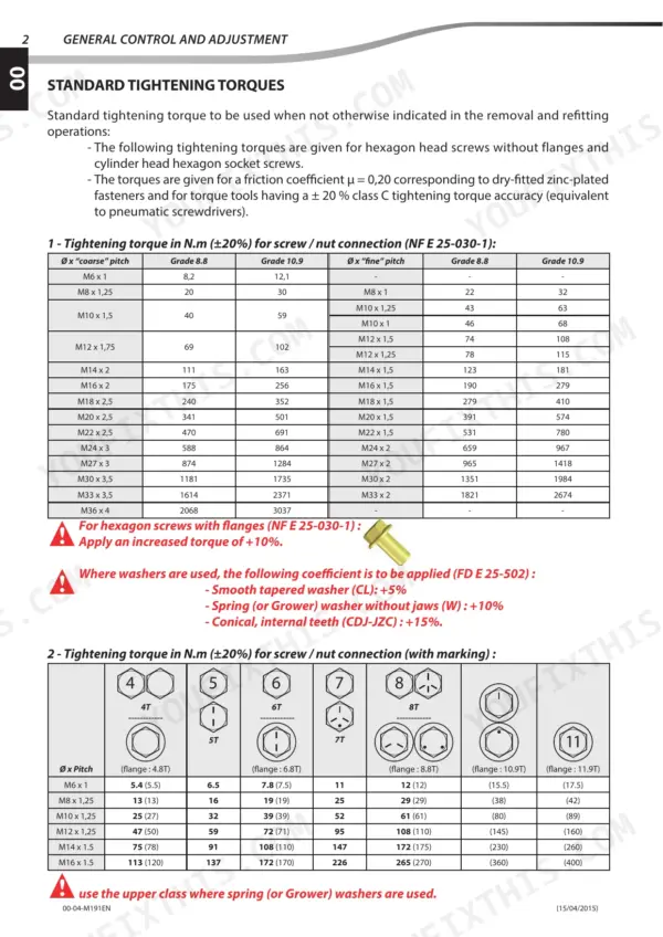
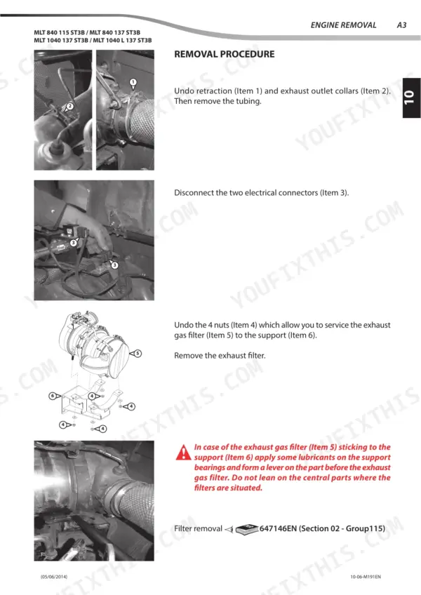
| Exhaust clamp torque | 20 N.m ±2% | p. 56 |
| Exhaust bracket bolt torque | 42 N.m ±3% | p. 56 |
| Relief valve 3 (Item 5) pressure setting | 80 ± 5 bar | p. 320 |
| Starter control relay K21 Current | 20/30A | p. 435 |
| Starter control rely K21 Current | 30A | p. 435 |
| Engine Oil Capacity | 13 Liters | p. 24 |
| Cooling System Capacity | 23 Liters | p. 24 |
| Fuel Tank Capacity | 143 Liters | p. 24 |
| Transmission Gear Box Oil Capacity | 23 Liters | p. 24 |
| Exhaust Filter Support Tightening Torque | 42 N.m ±3% | p. 56 |
| MLT 840 / MLT-X 840 | ||
| Hydraulic Oil Tank Capacity | 175 Liters | p. 24 |
| MLT 1040 / MLT-X 1040 | ||
| Hydraulic Oil Tank Capacity | 195 Liters | p. 24 |
Manitou MLT 840, MLT 1040 Common Problems This Manual Covers
Manitou MLT 840 and 1040 starter control relay K21 fault, engine intermittently not cranking when key is turned
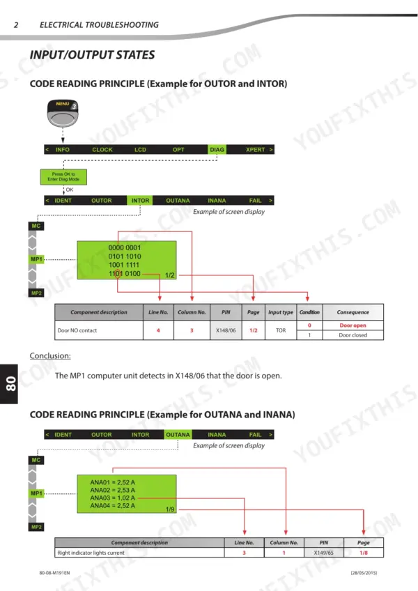
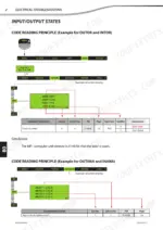
Check starter control relay K21 first; page 435 lists it at 20/30A, so confirm the replacement relay matches that rating. Then read the input/output states for the start circuit using the electrical troubleshooting steps, and pull any stored DTC against the error code reference before replacing parts.
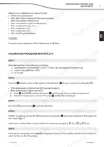
Manual Section: Electrical TroubleshootingTransmission throwing DTC error codes after gearbox work, gearbox calibration error showing on display
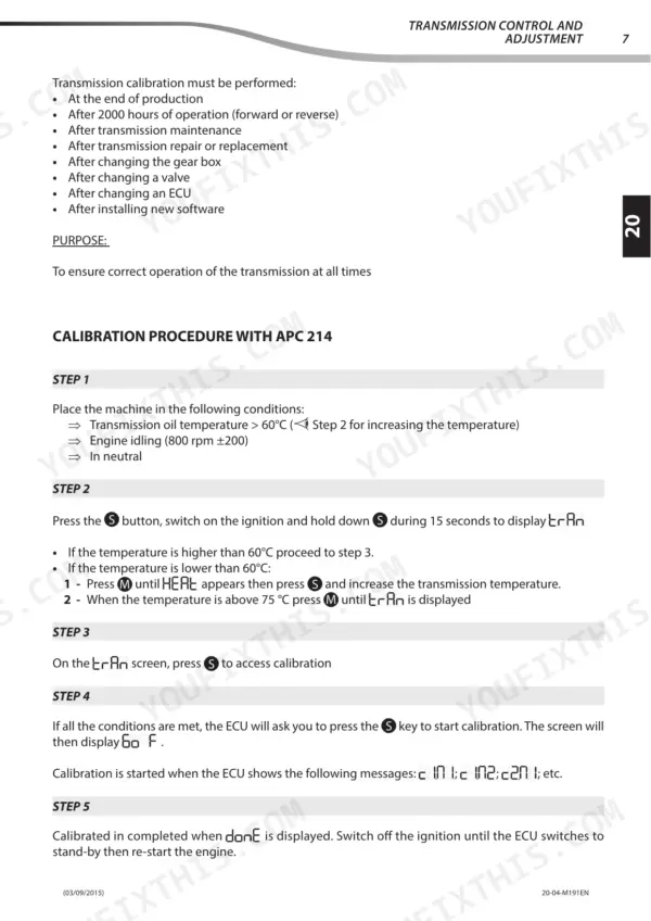
Read the transmission DTC before touching anything, then run the gearbox calibration procedure on page 166 and continue through page 167. Clear the code and recheck. If the calibration error returns, work through the transmission troubleshooting section for that specific DTC instead of throwing parts at the gearbox.
Manual Section: Transmission Troubleshooting p. 166Hydraulic relief valve 3 pressure out of specification, low pressure reading at the test port
Test relief valve 3 (Item 5) with a gauge on the correct pressure test port and compare the reading against 80 ± 5 bar listed on page 320. Adjust the valve if it sits outside that band, and trace the circuit on the hydraulic schematic before pulling components.
Manual Section: Hydraulic p. 320Exhaust filter soot level climbing with regeneration error code active on the display
Check the soot level and the regeneration mode the system is requesting, then read the regeneration error code before starting a regeneration. Inspect the exhaust filter mounting while you are there: torque the support to 42 N.m ±3% and the exhaust clamps to 20 N.m ±2%, both listed on page 56.
Manual Section: Engine Regeneration TroubleshootingBrake inching adjustment off and parking brake out of setting after brake work
Bleed the brake circuit first using the bleeding procedure in the brake troubleshooting section, since air will throw off every check after it. Then adjust the inching to spec and reset the parking brake settings. Recheck both with the machine on level ground before returning it to work.
Manual Section: Brake System TroubleshootingTelescopic boom extension and retraction out of adjustment, telescope sections needing shims reset
Inspect the telescope through a full extension and retraction cycle with the boom unloaded, watching for uneven travel. Adjust the telescope following the Boom Control and Adjustment procedure, then install shims where the procedure calls for them. Recheck the full stroke after shimming before putting a load back on the boom.
Manual Section: Boom Control and AdjustmentFrequently Asked Questions
What tightening torques apply to the engine suspension assembly on the Manitou MLT 840 and MLT 1040?
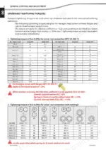
The engine suspension assembly drawing on page 54 lists two tightening torques, 230 N.m ±23 and 110 N.m ±11. Each value is tied to its bolt position in the drawing, so match the position before you torque.
What is the recommended engine oil capacity for the John Deere 4045 PWX engine on Manitou telehandlers?
The engine oil capacity for the John Deere 4045 PWX engine is 13 Liters. p. 24
What is the procedure for bleeding the hydraulic brake circuit on Manitou telehandlers?
To bleed the brake circuit, use a bleeder set to 1 to 1.2 bar. Connect a transparent recovery hose to the bleed screw (VP), operate the bleeder, and loosen the screw until fluid flows without air bubbles. Repeat this for all three front and rear bridge vent screws and the trailer brake valve, then top up with Shell LHM S fluid. p. 73
What is the required coolant capacity for the cooling system on Manitou telehandlers?
The cooling system capacity for the machine is 23 Liters. p. 24
During engine refit on the Manitou MLT 840 and MLT 1040, what torque goes on the 9 screws around the box perimeter?
Page 114 (Engine Refit) calls for 95 N.m ±10% on the 9 screws around the perimeter of the box (Item 2 and Item 5). Five of them (Item 5) sit on the gearbox side.
Do I get instant access to this Manitou MLT 840 115 ST3B Repair Manual?
One searchable PDF covering 647 pages, delivered instantly. No disc, no shipping, no waiting on the post.
Can I print just the pages I need from this Manitou MLT 840 115 ST3B manual?
Yes. Printing works from any reader and any printer, for your own shop use.

Reviews
There are no reviews yet.