
Printed by Manitou under document number 647541EN, this 527-page Manitou MLT 840 repair manual PDF is the factory workshop book for the MLT 840 115 PS, 840 137 PS and 1040 L 137 PS JD ST4 S1 telehandlers. Hydraulics and electrics fill nearly half the book: hydraulic schematics follow the circuits through the boom, leveling and counterbalance valves, while wiring diagrams and fault code tables point you to the circuit behind the problem. Engine, boom and brake chapters run from specifications through removal and refit, and the boom and brake sections name the specific tooling each job calls for. Set the counterbalance valve timing delay screw to 17.5 +0/-0.5 mm, and check the transmission safety valve at 9 bar. A parked telehandler costs you every hour it waits. Text-searchable pages and chapter bookmarks take you straight to the right procedure, and the machine back to lifting.
What's Inside This Manitou MLT 840, 1040 ST4 S1 Repair Manual
| System | Pages | Key Topics |
|---|---|---|
| General Instructions and Safety Notice | 5-26 | Preamble, Maintenance Position, Rules for Maintenance |
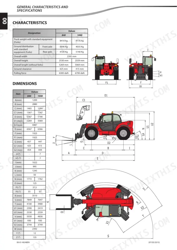
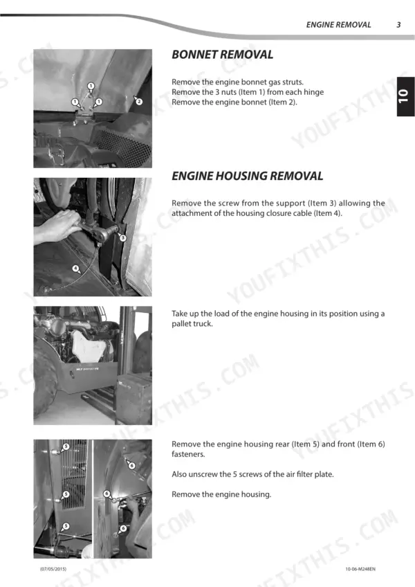
| Engine | 27-96 | Engine Characteristics and Specifications, Engine Components Location, Engine Control and Adjustment, Engine Removal, Engine Refit |
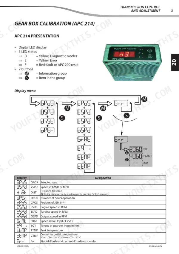
| Transmission | 97-134 | Transmission Characteristics and Specifications, Transmission Schematic Diagrams, Transmission Components Location, Transmission Control and Adjustment |
| Axle Assembly - Axle | 135-140 | Axle Control and Adjustment |
| Brake | 141-178 | Brake Characteristics and Specifications, Brake Control and Adjustment, Brake Removal, Brake Refit, Specific Brake Tooling |
| Telescopic Boom | 179-264 | Boom Characteristics and Specifications, Boom Schematic Diagrams, Boom Components Location, Boom Control and Adjustment, Boom Removal, Boom Refit, Specific Boom Tooling |
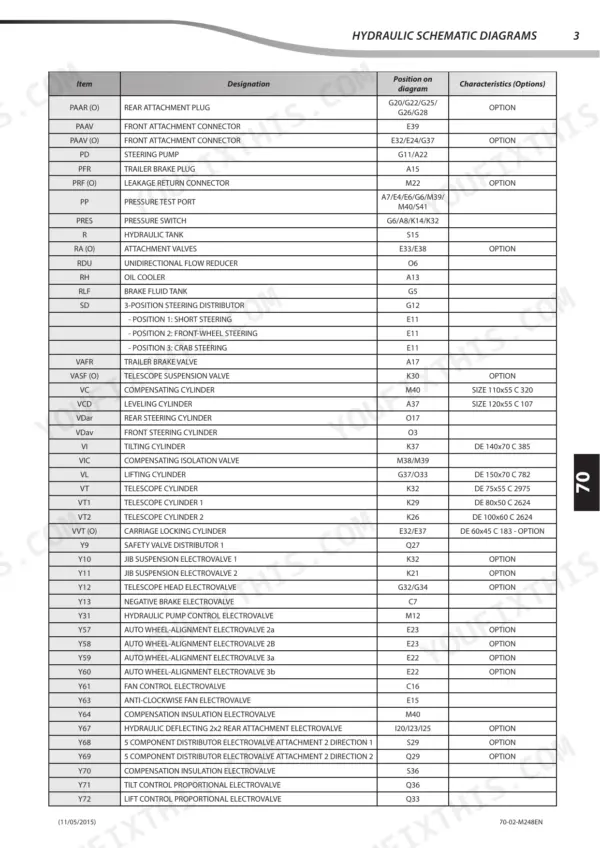
| Hydraulic | 265-376 | Hydraulic Characteristics and Specifications, Hydraulic Schematic Diagrams, Hydraulic Components Location, Hydraulic Control and Adjustment, Hydraulic Components Refit |
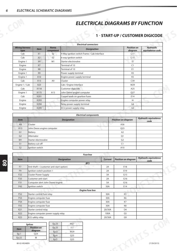
| Electricity | 377-500 | Electrical Characteristics and Specifications, Electrical Schematic Diagrams, Electrical Components Location, Electrical Control and Adjustment, Electrical Troubleshooting |
| Driver Cab | 501-518 | Driver Cab Components Location, Driver Cab Control and Adjustment, Driver Cab Removal, Driver Cab Refit |
| Frame - Body | 519-522 | Frame - Body Control and Adjustment |
| Options - Accessories | 523-527 | Options - Attachments Characteristics and Specifications |
Quick Reference Specifications
| Specification | Value | Page |
|---|---|---|
| Fuel tank capacity | 145 l | p. 25 |
| DOC turbo pipe clamp (Item 45) tightening torque | 20 N.m ±10% | p. 92 |
| DOC turbo pipe clamp (Item 46) tightening torque | 6.8 N.m ±10% | p. 92 |
| Counterbalance valve timing delay screw adjustment clearance | 17.5 +0/-0.5 mm | p. 346 |
| Leveling cylinder mounting bracket screws tightening torque | 190 Nm ± 28.5 N.m | p. 349 |
| Valve By-pass pressure | 3.44 - 3.94 bar | p. 107 |
| Safety valve pressure | 9 bar | p. 107 |
| Main pressure regulator pressure | 18-21 bar | p. 114 |
| Converter inlet pressure | 2-5 bar | p. 114 |
| Nominal pressure | 140 bar | p. 284 |
| Nominal flowrate | 25 liters/minute | p. 284 |
| B5207 EGR Temperature Sensor Resistance at 40°C | 26065 Ω | p. 410 |
Manitou MLT 840, 1040 ST4 S1 Common Problems This Manual Covers
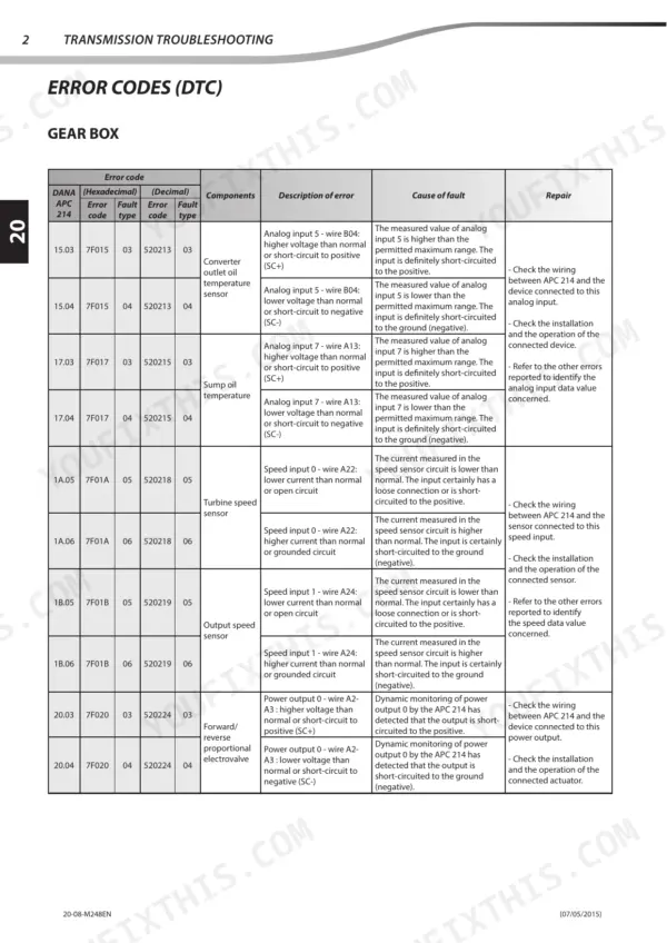
Manitou MLT 840 and 1040 transmission gearbox logging a DTC error code during operation
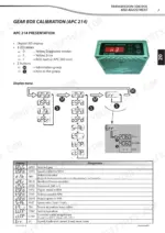
Read the stored gearbox DTC and match it against the transmission error code table on page 120 before you pull anything apart. Where the fault points to gearbox calibration, run the calibration procedure on page 115 with the machine parked safely, then recheck the DTC list to confirm the code has cleared.
Manual Section: Transmission Troubleshooting p. 120Transmission main pressure or clutch pressures out of range on forward, reverse and gear checks
Measure main pressure regulator pressure following page 114 and confirm 18-21 bar. Check 1st, 2nd and 3rd gear, high-speed and low-speed forward clutch, and reverse clutch pressures against the same 18-21 bar. Converter inlet and outlet should each read 2-5 bar. Then verify relief valve pressure at 19.5-22 bar and safety valve at 9 bar on page 107.
Manual Section: Transmission p. 114Hydraulic load sensing circuit with LS regulator or LS relief valve pressure below specification
Check the hydraulic oil level first (tank capacity 169/189L, page 25). Measure LS regulator pressure following page 286 and confirm 248 bar, then check the LS relief valve setting against 300 bar. If the hydraulic pump has to come off, torque the mounting screws to 105 N.m ±5% on refit, as shown on page 342.
Manual Section: Hydraulic p. 286Counterbalance valve timing delay screw out of adjustment after hydraulic component removal and refit
Measure the timing delay screw adjustment clearance on the counterbalance valve following page 346 and set it to 17.5 +0/-0.5 mm. The tolerance only runs short, so never leave it longer than 17.5 mm. Recheck the dimension after everything is tightened back up and before the machine goes back to work.
Manual Section: Hydraulic p. 346B5207 EGR temperature sensor giving a bad reading or setting an electrical DTC
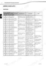
Check the electrical DTC against the error code table, then unplug B5207 and measure its resistance. Expect 26065 Ω at 40°C and 892.8 Ω at 150°C, as listed on page 410. If the sensor reads within spec, trace its circuit on the electrical wiring diagrams for a damaged connection.
Manual Section: Electricity p. 410DOC to turbo pipe clamps loose or not seated after engine removal and refit
Torque the DOC turbo pipe clamps following page 92: Item 45 takes 20 N.m ±10% and Item 46 takes 6.8 N.m ±10%. Those values are far apart, so match each clamp to its item number before you put a wrench on it. Check the pipe is seated squarely in both joints before final torque.
Manual Section: Engine p. 92Frequently Asked Questions
How do I clear error codes on the Manitou MLT 840 or 1040 transmission?
To clear error codes for the transmission, you must use the PAD diagnostic tool. The procedure for replacing the gearbox ECU or clearing data is found in the PAD Diagnostic menu under 'ECU replacement'. p. 114
What is the procedure for calibrating the brake pedal on the MLT 840/1040?
Calibration of the brake pedal must be performed with the engine running. Access the 'BRAKE' menu on the cluster display, enter the customer code, and follow the steps to release and then fully depress the pedal, ensuring voltage values are between 0.5V and 4.5V. p. 150
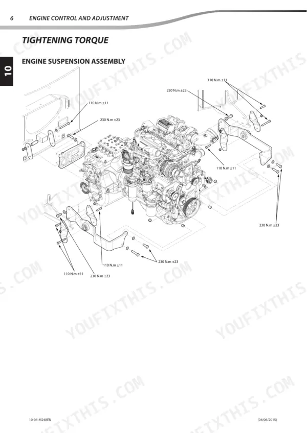
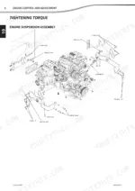
What is the correct tightening torque for the engine suspension assembly on the Manitou MLT 840 and MLT 1040?
The engine suspension assembly requires a tightening torque of 110 N.m ±11 for specific bolts and 230 N.m ±23 for others, as indicated in the engine suspension assembly diagram. p. 46
What is the required amount of coolant to load for the Manitou E134a air conditioning equipment?
The specified amount of coolant to load for the Manitou E134a air conditioning equipment is 950g ± 50g. p. 508
What is the procedure for bleeding the hydraulic brake circuit?
To bleed the brake circuit, use a bleeder at a pressure of 1 to 1.2 bar. Fit the brake bleeder adapter to the tank, then open each bleed screw starting from the one furthest away from the master cylinder until the fluid flows without air bubbles. p. 154
Is this Manitou MLT 840 manual a download or a disc?
A single searchable PDF file of 527 pages, downloadable right after payment. Nothing ships, nothing waits in the mail.
Can I print just the pages I need from this Manitou MLT 840 manual?
Yes. Print a chapter or just the pages for the job at hand, for use in your own shop. Any home or office printer works.


Reviews
There are no reviews yet.