
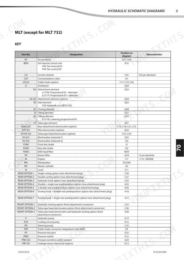
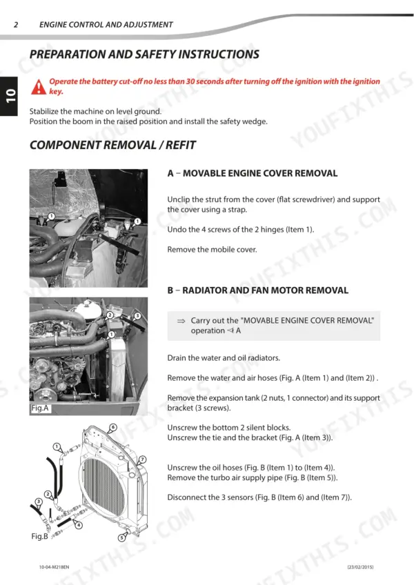
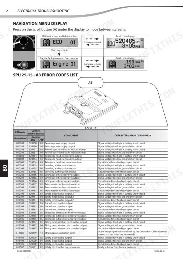
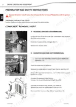
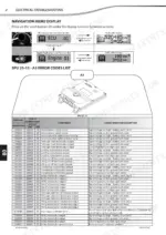
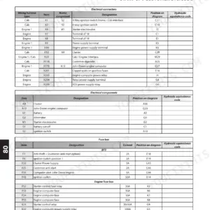
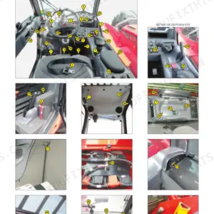
A boom that drifts under load on your Manitou MLT 634 120 ST3B is the kind of job this 449-page repair manual (OEM ID 647412EN) was written for, and it covers 14 ST3B telehandler variants across the MLT and MT ranges. Electricity is the biggest chapter, at more than a third of the book, with wiring schematics that trace harness routing and fault code tables that explain each stored error. Hydraulic schematics map the boom and attachment circuits, and the transmission chapter includes its own troubleshooting section. Torque the axle fasteners to 340 N.m ± 10%, and the engine oil pressure relief valve should open at 9 bar. A made-up figure on a loaded axle can cost you a wheel. Bookmarks take you from the cover to the brake or boom chapter in two clicks, and the text layer finds any spec by name.
What's Inside This Manitou MLT 634–741, MT 732–1030 ST3B Repair Manual
| System | Pages | Key Topics |
|---|---|---|
| General Instructions and Safety Notice | 4-25 | Preamble, Maintenance Position, Rules for Maintenance |
| Engine | 26-79 | Engine Characteristics and Specifications, Engine Circuits Flow Diagram, Engine Components Location, Engine Control and Adjustment, Engine Removal, Engine Refit |
| Transmission | 80-115 | Transmission Schematic Diagrams, Transmission Components Location, Transmission Control and Adjustment, Transmission Removal, Transmission Troubleshooting |
| Axle Assembly - Axle | 116-119 | Axle Control and Adjustment |
| Brake | 120-137 | Brake Characteristics and Specifications, Brake Components Location, Brake Control and Adjustment, Brake Removal |
| Telescopic Boom | 138-159 | Boom Characteristics and Specifications, Boom Components Location, Boom Control and Adjustment, Boom Removal |
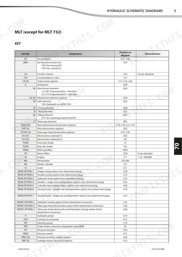
| Hydraulic | 160-239 | Hydraulic Characteristics and Specifications, Hydraulic Schematic Diagrams, Hydraulic Components Location, Hydraulic Control and Adjustment, Hydraulic Components Removal |
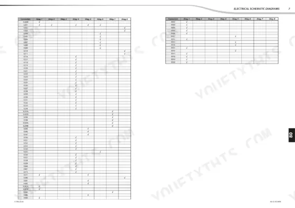
| Electricity | 240-411 | Electrical Characteristics and Specifications, Electrical Schematic Diagrams, Electrical Components Location, Electrical Control and Adjustment, Electrical Components Removal |
| Options - Accessories | 412-449 | Machine Option Configuration, Forced Operation Option, Crc Option Telescope Suspension, E.C.S. Option Easy Connecting System, Manual Accelerator Option, Air-Conditioning Option |
Quick Reference Specifications
| Specification | Value | Page |
|---|---|---|
| Engine support bracket bolt torque | 70 N.m ± 10% | p. 68 |
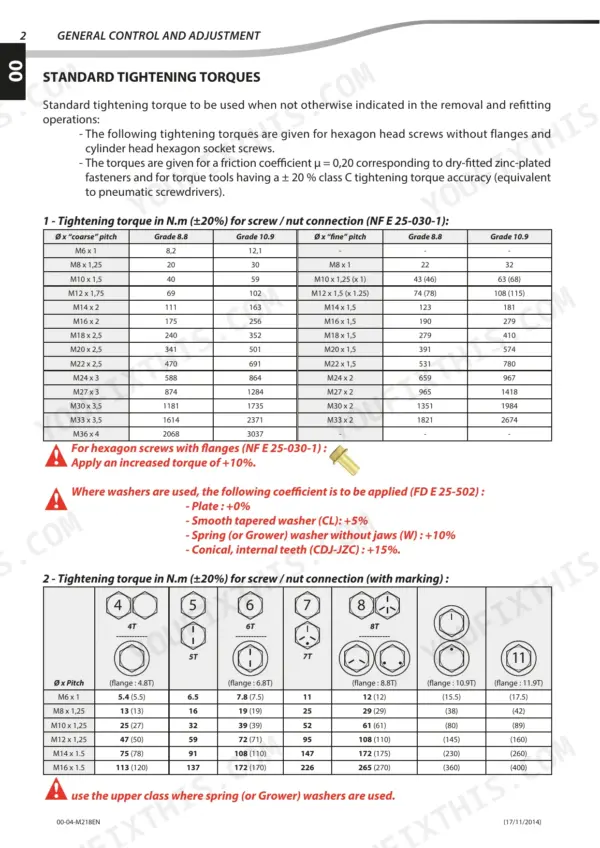
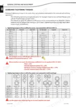
| Axle tightening torque | 340 N.m ± 10% | p. 119 |
| Pressure relief valve opening pressure | 9 bar | p. 32 |
| Maximum oil temperature in the sump | 125°C | p. 32 |
| Maximum cooling system pressure | 1.2 bar | p. 33 |
| Maximum temperature difference across the radiator | 8°C | p. 33 |
| Main L.P. pressure | 15 bar | p. 94 |
| Converter L.P. pressure | 6 bar | p. 94 |
| Slide pad tightening torque C1 | 15 N.m ±15% | p. 147 |
| Slide pad tightening torque C2 | 92 N.m ±15% | p. 147 |
| Fuel tank capacity | 120 L | p. 19 |
| Engine oil capacity | 10 L | p. 19 |
Manitou MLT 634–741, MT 732–1030 ST3B Common Problems This Manual Covers
Manitou MLT and MT ST3B telehandler engine starts with difficulty, runs erratically, or lacks power under load
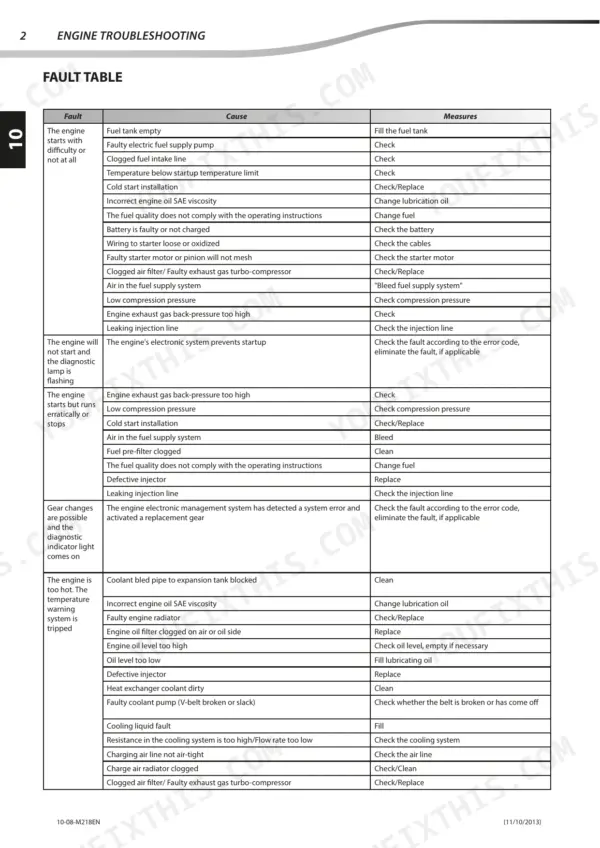
Verify idle speed at 930 rpm and maximum unladen speed at 2360 rpm against page 29 before chasing anything else. Then work through the engine fault table on page 73, matching your symptom (hard start, erratic running, lack of power, smoke) to its listed causes. Fix the first cause it points to, then retest.
Manual Section: Engine TroubleshootingEngine overheating with coolant temperature climbing past thermostat range during sustained work
Test the thermostat against page 33: it should open at 92°C with a 110°C maximum. Measure coolant temperature at the radiator inlet and outlet and compare the difference against the 8°C maximum. Pressure test the system without exceeding 1.2 bar, then confirm a full 20.5 L charge per page 19.
Manual Section: Engine p. 33PG 115 six-speed transmission logging gear box error codes or showing abnormal pressures at test points
Check the gear box error code against the tables starting, then follow the transmission error verification flow chart. Measure pressures at the test points against page 99: pump (T3) 15 to 18 bar, converter (T1) 5 to 8 bar, lubrication (T5) 0.75 to 1.25 bar. Write down each reading before pulling anything apart.
Manual Section: Transmission p. 99Hydraulic actuators moving abnormally and control block not operating as it should
Check hydraulic oil level first; the tank holds 135 L per page 19. Inspect the circuit for visually observable defects before touching any adjustment. Then connect the basic manometer set from page 237, choosing the gauge range (0/400 or 0/600 bar) to suit the circuit, and work the abnormal operation checks in Hydraulic Control and Adjustment.
Manual Section: Hydraulic Control and AdjustmentTelescopic boom slide pads loose and tube slip faces dry when extending and retracting
Torque the slide pad fasteners to page 147 values: 15 N.m ±15% at C1 and 92 N.m ±15% at C2. Clean the tube slip faces, then spread grease at 0,2 kg/m² as page 155 specifies. Cycle the boom fully in and out to distribute it before checking pad seating again.
Manual Section: Telescopic Boom p. 147LLMI, SPU 25-15, hydraulic pump or engine ECU reporting active error codes
Check which controller set the fault, then match the code in the error code lists starting on page 375 (SPU, engine ECU DTC, hydraulic pump, LLMI). Verify connectors and continuity along the affected circuit with the wiring diagrams before condemning a controller. Note the code number before you shut the machine down.
Manual Section: Electrical TroubleshootingFrequently Asked Questions
How do I clear transmission error codes on a Manitou MLT 735 120 PS ST3B?
To clear transmission error codes, you must first identify the defective harness by holding down the '-' button on the JSM gear selector while switching the ignition off and then on again. The display will show the letter 'E' followed by a number indicating the faulty harness. Once the fault is repaired, the indicator will go off, though some faults require switching off the ignition and waiting 30 seconds before restarting. p. 109
What is the procedure for bleeding the trailer brake circuit?
To bleed the trailer brake circuit, use a brake bleeder set to a pressure of 1 to 1.2 bar. Remove the transmission cover plate and the lower left-hand dashboard cover to access the brake fluid tank. Fit the brake bleeder adapter to the tank, place a transparent tube on the trailer brake valve bleed screw, and operate the bleeder until fluid flows without air bubbles. p. 135
What is the tightening torque for the engine shock absorber screws on the Manitou MLT 634-741, MT 732-1030 ST3B?
The engine shock absorber screws must be tightened to 35 N.m. Specifically, screw no. 2 and screw no. 3 require the application of medium thread lock during installation. p. 56
What is the correct oil capacity for the cooling system on the Manitou MLT 634-741, MT 732-1030 ST3B?
The cooling system requires 20.5 liters of cooling liquid, which should provide protection down to -35°C. p. 19
What is the maximum hydraulic pump pressure on the Manitou MLT 634-741, MT 732-1030 ST3B?
The maximum working pressure for the Casappa MVP 60 pump is 315 bar for the pressure limiter. p. 189
What exactly do I receive with this Manitou MLT 634 120 ST3B Repair Manual?
One searchable PDF covering 449 pages, delivered instantly. No disc, no shipping, no waiting on the post.
Does this Manitou MLT 634 120 ST3B manual allow printing?
Yes. Print the sections you need to take out to the shop for your own use. Standard letter or A4 paper works.


Reviews
There are no reviews yet.