
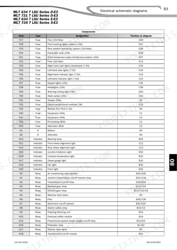
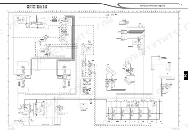
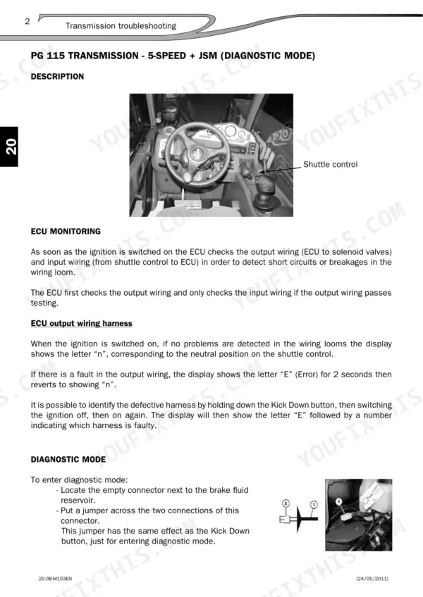
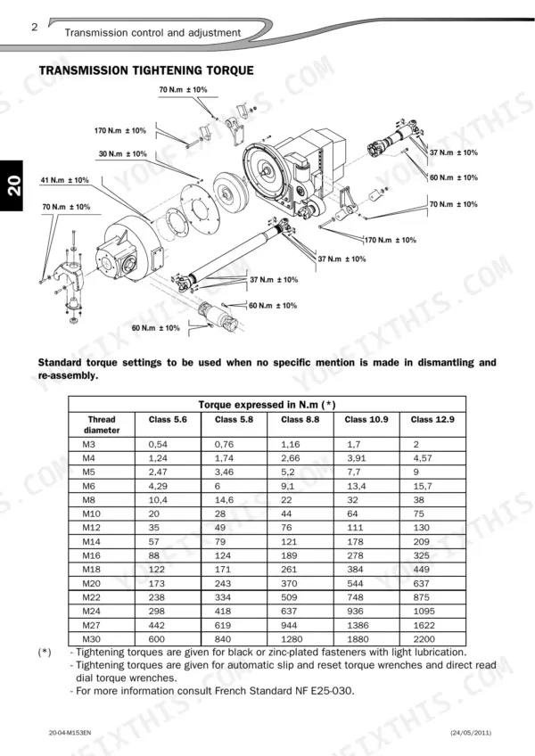
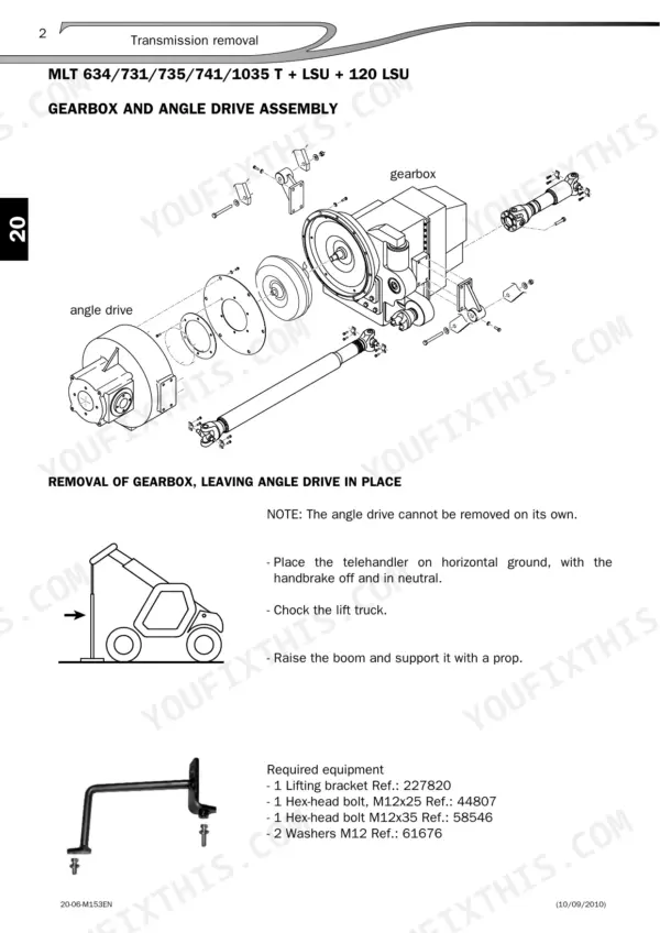
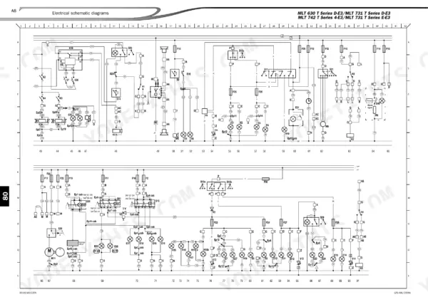
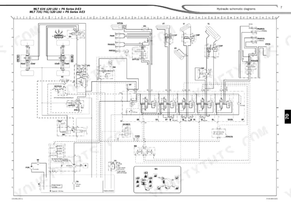
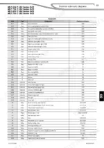
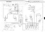
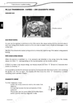
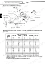
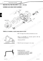
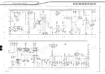
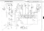
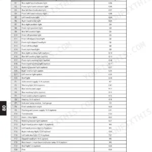
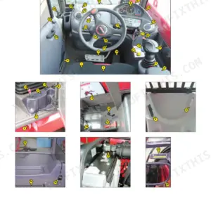
What a Manitou telehandler's transmission, boom and hydraulics should read under test is settled in one place: repair manual 00-M153EN, 579 pages written for eleven MLT and MT models on the 1104 D Euro 3 engine. Hydraulic and electrical chapters fill well over half of this Manitou MT 932 repair manual PDF, with schematics tracing every circuit and location pages naming each valve, sensor and connector you find on the machine. Transmission work runs from removal to dedicated troubleshooting charts, and the axle, brake and boom chapters cover adjustment and removal in turn. Set main low pressure to 15 bar and the converter to 6 bar, then torque fuel circuit fittings to 26 N.m ± 10%. Slipping transmissions under load are slow faults to find. Bookmarks for all nine chapters and a searchable text layer put the right schematic on your screen in seconds.
What's Inside This Manitou MLT 630 to MT 1033 Repair Manual
| System | Pages | Key Topics |
|---|---|---|
| General Instructions and Safety Notice | 4-11 | Preamble, Maintenance Position, Rules for Maintenance |
| Engine | 12-29 | Engine Characteristics and Specifications, Engine Control and Adjustment |
| Options - Accessories | 30-75 | Option Forced Operation, CRC Option: Boom Suspension, Cleanfix Option, ECS (Easy Connecting System) Option |
| Transmission | 76-113 | Transmission Components Location, Transmission Control and Adjustment, Transmission Removal, Transmission Troubleshooting |
| Axle Assembly - Axle | 114-133 | Axle Control and Adjustment, Axle Removal |
| Brake | 134-159 | Brake Characteristics and Specifications, Brake Components Location, Brake Control and Adjustment, Specific Brake Tools |
| Telescopic Boom | 160-223 | Boom Control and Adjustment, Boom Removal |
| Hydraulic | 224-379 | Hydraulic Characteristics and Specifications, Hydraulic Schematic Diagrams, Hydraulic Components Location, Hydraulic Control and Adjustment |
| Electricity | 380-579 | Electrical Characteristics and Specifications, Electrical Schematic Diagrams, Electrical Components Location, Electrical Control and Adjustment |
Quick Reference Specifications
| Specification | Value | Page |
|---|---|---|
| All Models | ||
| Cooling circuit fan bolt torque | 20 N.m ± 10% | p. 27 |
| Fuel circuit fitting torque | 26 N.m ± 10% | p. 28 |
| Cold start valve | 26 bar | p. 79 |
| Main L.P. | 15 bar | p. 79 |
| Slide pad nut torque | 92,6 N.m ± 25% | p. 168 |
| Priority valve seat torque | 10 Nm | p. 339 |
| Hydraulic control unit torque | 10 Nm | p. 339 |
| Steering pressure | 140 bar | p. 290 |
| Brake power assistance pressure | 35 bar | p. 291 |
| MLT 1035 LT LSU | ||
| Axle mounting bolt torque | 340 N.m ± 10% | p. 117 |
| MT 732/932 | ||
| Main pressure relief valve | 240 bar | p. 288 |
| MLT 630/731 | ||
| Main pressure relief valve | 250 bar | p. 288 |
Manitou MLT 630 to MT 1033 Common Problems This Manual Covers
Manitou MLT and MT telehandler hydraulic control block showing lack of power and lack of speed on movements
Check stand-by pressure first using the Hydraulic Pressure Control procedure on page 292; it should read 19 bar ± 1. Then test main circuit pressure against the relief valve setting listed for your exact model on page 288, because MT and MLT settings differ. Work through the control block troubleshooting table before replacing parts.
Manual Section: Hydraulic Control Block TroubleshootingTransmission ECU reporting a fault with input or output monitoring showing an abnormal reading
Check the transmission ECU in diagnostic mode following page 109, then read the input and output monitoring to isolate the faulty circuit. Measure main L.P. pressure against 15 bar and converter L.P. pressure against 6 bar per page 79. Confirm the cause before committing to transmission removal.
Manual Section: Transmission Troubleshooting p. 109Hydraulic control block steering circuit problem with poor or weak steering response at the wheel
Test steering circuit pressure using the Hydraulic Pressure Control procedure on page 290 and verify it reaches 140 bar, which applies to all models in this manual. If you service the priority valve, torque its seat to 10 Nm per page 339, then recheck steering pressure before returning the machine to work.
Manual Section: Hydraulic Pressure Control p. 290Hydraulic control block spool leaking oil and hydraulic functions malfunctioning during simultaneous movements
Inspect each spool section on the control block for external leakage. Run the hydraulic control block troubleshooting table for simultaneous movement faults, then verify stand-by pressure at 19 bar ± 1 per page 292. When refitting the hydraulic control unit, torque it to 10 Nm and the EMS module to 15 Nm per page 339.
Manual Section: Hydraulic Control Block TroubleshootingHydraulic pilot control unit joystick not returning properly, with a loose handgrip and oil seepage
Torque the joystick hand-grip nut to 40 N.m ± 10% as listed on page 523, then recheck for play in the handgrip. Inspect the pilot control unit for oil seepage and test that the joystick returns cleanly from every direction. If movement speed is still low, work through the pilot control unit troubleshooting table.
Manual Section: Hydraulic Pilot Control Unit Troubleshooting p. 523Longitudinal stability warning device faulty, with a suspect strain gauge connection or electrical fault
Inspect the strain gauge connections and their wiring first, since a bad connection is the cheapest fix. Run the electrical checks in the Longitudinal Stability Warning Device troubleshooting section, then measure strain gauge resistance and compare your reading with the values that section lists. Do not condemn the gauge until connections test good.
Manual Section: Longitudinal Stability Warning Device TroubleshootingFrequently Asked Questions
How do I bleed the hydraulic brake circuit?
To bleed the brake circuit, use a pressurized brake bleeder set to 1 to 1.2 bar (Ref. 554 019). Start with the most distant bleed point (rear axle) and work towards the nearest (front axle), loosening the vent screw until fluid flows without air bubbles. Top up the brake fluid tank level using Manitou hydraulic ISO 46 fluid. p. 150
What is the cylinder head tightening torque on a flanged cylinder for the Manitou MLT 630 to MT 1033?
The tightening torque for the cylinder head depends on the thread diameter. For example, an M43 x 200 thread requires 200 to 250 N.m, while an M134 x 200 thread requires 450 to 500 N.m. Refer to the table on page 347 for specific values based on the thread size. p. 347
How often should I change the Cleanfix option filter on the Manitou MLT 630 to MT 1033?
The filter for the Cleanfix option should be changed every 500 hours of operation. The part number for the replacement filter is 781443. p. 67
How do I adjust the main pressure relief valve on the control block?
Connect a pressure gauge to the test port and run the engine at maximum revolutions. Activate the accessory circuit control and read the pressure. The main pressure relief valve should be set to 240 bar for MT 732/932 models or 250 bar for MLT 630/731 models. p. 288
How do I set the neutral position on the EMS module on a Manitou MLT 630 to MT 1033?
Ensure the 35 bar supply pressure is decompressed. Remove the inspection plug on the underside of the rear cover of the control module. Switch on the ignition and use a small straight screwdriver to turn the adjustment screw clockwise or anti-clockwise until the green LED lights up, indicating the mechanical zero point matches the electrical zero point. p. 318
How will I receive this Manitou MLT 630 Repair Manual?
All 579 pages arrive as one searchable PDF at checkout. Read it at the desk, then take the phone out to the machine.
Is this Manitou MLT 630 manual print-friendly?
Yes. Print a chapter or just the pages for the job at hand, for use in your own shop. Any home or office printer works.


Reviews
There are no reviews yet.