
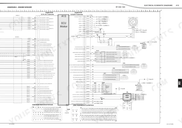
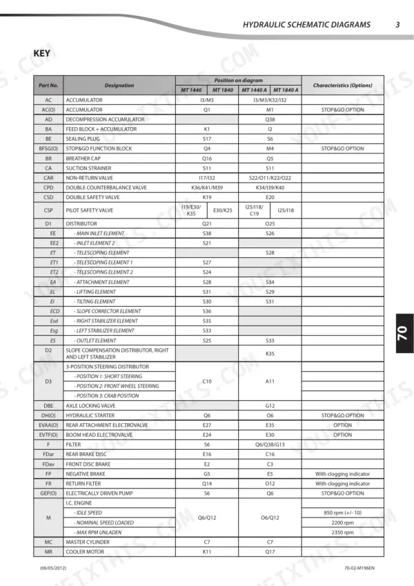
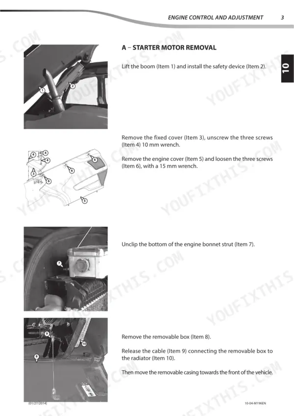
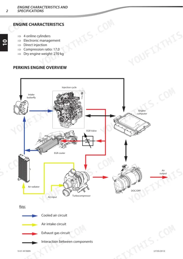
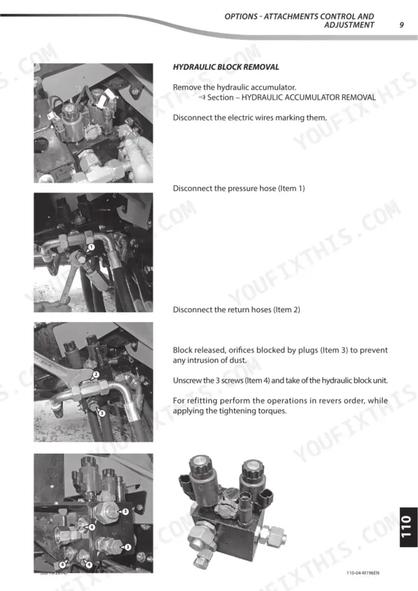
A boom that drifts or a cab display full of fault codes can park a telehandler for a week. Built for both jobs, the Manitou MT 1440 repair manual PDF is a 667-page factory book covering eight variants of the MT 1440 and 1840 telehandler series, A and ST3B builds included. Electrical work fills the biggest share: schematics by function, cable identification, ECU input and output tables, harness drawings, and a DTC section leading each code to its troubleshooting procedure. Hydraulic schematics come with control, adjustment and removal procedures; the transmission, brake and boom chapters name the specific tooling each job calls for. Set the main relief valve to 200 bar, and hold the gap between upper boom pad and shim to 0 to 0.5 mm. Shim a pad by feel and you pay for a second boom strip-down. Bookmarked and text-searchable, the PDF helps you pin down the exact component before you order, so the first one fits.
What's Inside This Manitou MT 1440 & MT 1840 Repair Manual
| System | Pages | Key Topics |
|---|---|---|
| General Instructions and Safety Notice | 4-21 | General Characteristics and Safety, Maintenance Position, Rules for Maintenance |
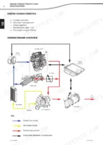
| Engine | 22-75 | Engine Characteristics and Specifications, Engine Components Location, Engine Control and Adjustment, Engine Removal, Engine Refit |
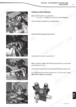
| Options - Accessories | 76-101 | Options - Attachments Characteristics and Specifications, Options - Attachment Components Location, Options - Attachments Control and Adjustment |
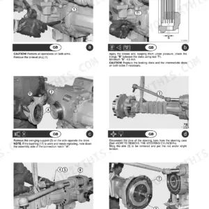
| Transmission | 102-135 | Transmission Schematic Diagrams, Transmission Components Location, Transmission Control and Adjustment, Transmission Removal, Specific Transmission Tooling |
| Axle Assembly - Axle | 136-137 | Axle |
| Brake | 138-157 | Brake Characteristics and Specifications, Brake Control and Adjustment, Brake Removal, Specific Brake Tooling |
| Telescopic Boom | 158-219 | Boom Characteristics and Specifications, Boom Schematic Diagrams, Boom Components Location, Boom Control and Adjustment, Specific Boom Tooling |
| Hydraulic | 220-337 | Hydraulic Characteristics and Specifications, Hydraulic Schematic Diagrams, Hydraulic Components Location, Hydraulic Control and Adjustment, Hydraulic Components Removal |
| Electrical Characteristics and Specifications | 338-423 | MT 1440-1840, ECU Inputs/Outputs, Electrical Component Data Sheets |
| Electrical Schematic Diagrams | 424-547 | Diagram Codes, Cable Identification, Multiplexing, Schematic Diagrams by Function |
| Electrical Components Location | 548-611 | 2D/3D Location, Harness Assembly, Frame Harness, Cab Harness, Engine Harness |
| Electrical Components Refit | 612-617 | Strain Gauge, Preparation and Safety, Refit Procedures |
| Electrical Troubleshooting | 618-651 | Input/Output Conditions, Code Reading Principle, Error Codes (DTC), Troubleshooting Procedures |
| Driver Cab | 652-667 | Driver's Cab Components Location, Driver's Cab Control and Adjustment, Driver's Cab Refit |
Quick Reference Specifications
| Specification | Value | Page |
|---|---|---|
| All Models | ||
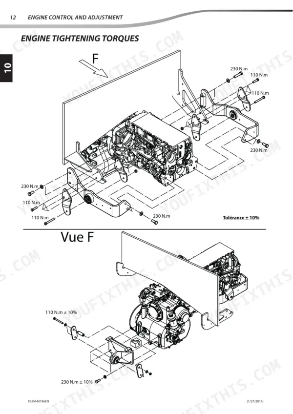
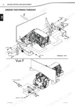
| Engine tightening torque | 110 N.m ± 10% | p. 47 |
| I.C. engine - idle speed | 850 rpm (+/- 10) | p. 280 |
| Clearance between upper pad and shim | between 0 and 0,5 mm | p. 197 |
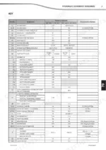
| Main relief valve calibration | 200 bar | p. 241 |
| LED voltage | 12V | p. 258 |
| Flow Regulating Valve Resistance | 10 Ω | p. 268 |
| MT 1440 ST3B | ||
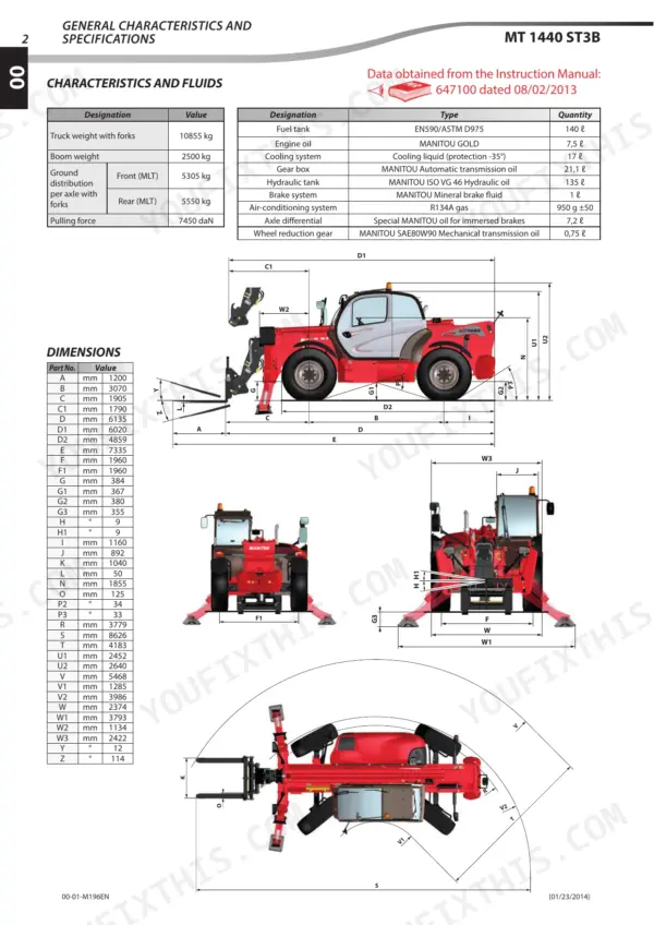
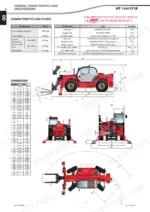
| Engine Oil Capacity | 7.5L | p. 13 |
| Hydraulic Tank Capacity | 135L | p. 13 |
| Fuel Tank Capacity | 140L | p. 13 |
| MT 1840 ST3B | ||
| Engine Oil Capacity | 7.5L | p. 14 |
| Hydraulic Tank Capacity | 135L | p. 14 |
| Fuel Tank Capacity | 140L | p. 14 |
Manitou MT 1440 & MT 1840 Common Problems This Manual Covers
Manitou MT 1440 hydraulic boom functions weak and slow under load, main hydraulic pressure low
Check the hydraulic oil level first, then connect a gauge at the main pressure test port and read main pressure. The pressure test port values table on page 305 gives 270 bar maximum. If pressure comes up short, work through the hydraulic control and adjustment checks before you replace any hydraulic components.
Manual Section: Hydraulic p. 305Telescopic boom sections loose with excess play between upper wear pad and shim
Measure the clearance between the upper pad and its shim with feeler gauges at each pad location. The spec on page 197 is between 0 and 0,5 mm. If the gap is over that, correct the shimming and recheck before the boom goes back to work.
Manual Section: Hydraulic p. 197Hydraulic function slow or dead, flow regulating valve not responding to control input
Measure flow regulating valve resistance at the connector with the harness unplugged; page 268 lists 10 Ω. Then check current with the circuit live against the 1.2 A maximum. A reading well off that resistance points to the valve, while good readings send you to the electrical troubleshooting procedures on page 618.
Manual Section: Hydraulic p. 268Engine idle speed hunting or set wrong, max unladen rpm not reaching spec
Check engine speed with a tachometer once the engine is at operating temperature. Idle should sit at 850 rpm (+/- 10), nominal loaded speed at 2200 rpm, and max unladen at 2350 rpm, all listed on page 280. If readings drift, work through the engine troubleshooting procedure on page 22 before adjusting anything.
Manual Section: Engine Troubleshooting p. 22Engine ECU fails to wake up at ignition key on, engine will not start
Check fuse F31, the engine ECU wake-up fuse rated 5A, and fuse F43 for the ignition switch rated 50A, both shown on page 346. Replace any blown fuse with the correct rating, then read stored error codes (DTC) and follow the electrical troubleshooting procedures on page 618 if the ECU still stays dark.
Manual Section: Electrical Characteristics and Specifications p. 346Error codes cannot be read, no power or communication at the diagnostic plug
Check both diagnostic plug fuses, F28 and F33, each rated 5A on page 346. Replace a blown fuse with the same rating and retest the connection. Once communication is back, follow the code reading principle and error code (DTC) tables in the electrical troubleshooting section starting on page 618.
Manual Section: Electrical Troubleshooting p. 618Frequently Asked Questions
What is the torque specification for the engine mounting screws on the MT 1440/1840?
The tightening torque for the engine suspension arm screws (Item 4, L=45 mm) is 230 N.m ± 10%. Other engine mounting screws have different specifications, such as 110 N.m ± 10% for specific suspension arm bolts as detailed in the engine tightening torques diagram. p. 65
What are the boom wear pad replacement specs for the Manitou MT 1440 and MT 1840 telehandlers?
When replacing wear pads, you must measure the clearance between the telescopes and insert shims to fill the gap. For the T3 telescope, the shim thickness should be J1/2, and for the T2 telescope, it should be J3/2. The total clearance after adjustment should be between 0 and 0.5 mm. Tightening torque for pad nuts is 15 N.m ± 15% for C1 and 92 N.m ± 15% for C2. p. 197
What is the required coolant capacity for the MT 1440 ST3B engine?
The cooling system for the MT 1440 ST3B requires 17 liters of cooling liquid with protection down to -35°C. p. 13
What is the procedure for bleeding the rear axle locking cylinders?
Bleeding should be carried out cold if possible. Disconnect the electrovalves (Items 1 and 2) from the cylinders, start the machine, and install a capillary on the right-hand cylinder (Item 3) MINIMESS coupling (Item 5) to recover oil in a container. Repeat this process for the left-hand cylinder (Item 4) using the MINIMESS coupling (Item 6). p. 308
Will this Manitou MT 1440 Repair Manual download right away?
You get a 667-page searchable PDF that downloads instantly after checkout. Open it on your laptop, tablet, or phone, and bring it right to the shop floor.
Does this Manitou MT 1440 manual allow printing?
Yes. Many buyers print one chapter at a time for their own shop and keep the rest on a tablet.
Can I trace hydraulic lines with this Manitou MT 1440 manual?
Yes. The manual includes hydraulic circuit diagrams, system schematics, and component specifications with pressure ratings. You can see one on page 282.

Reviews
There are no reviews yet.