
Within the hour you could have the rocker cover off a Perkins 1004 and a feeler gauge between rocker and valve tip. Set them cold: 0,20 mm inlet, 0,45 mm exhaust, working through firing order 1.3.4.2. This book covers the Manitou ML 632 and ML 635 through the MT 1740 SL, Série 2.
Few things are worse than a telehandler that revs hard but won't push into a pile. The shuttle transmission section covers the forward and backward line of force, clutch pressure checks and troubleshooting. You can test the transmission before you split anything.
The complete Perkins TPD 1350 workshop manual is bound in. Axles, brakes, boom, cylinders, hydraulic pressures, diagrams and the stability alarm are all covered. Work through it and the machine will lift and drive again.
What's Inside This Manitou ML 632, ML 635, MT 940 L, MT 1337 SL, MT 1740 SL Repair Manual
| System | Pages | Key Topics |
|---|---|---|
| General Instructions, Safety and Lift Truck Characteristics | 1-71 | Characteristics per Model (ML 632/635, MT 835-120 Ls, MT 845 to MT 1740 SL Série 2), Perkins Engine Type per Model, Transmission and Hydraulic Circuit Data, Dimensions and Load Charts, Filters, Lubricants and Capacities |
| Perkins New 1000 Series Workshop Manual: General Information and Specifications | 72-107 | Bound-In Perkins TPD 1350 Workshop Manual, Engine Identification, Specifications and Data |
| Engine: Cylinder Head, Pistons and Crankshaft | 108-185 | Cylinder Head Assembly, Valve Tip Clearance, Piston and Connecting Rod Assemblies, Crankshaft Assembly |
| Engine: Timing Case, Cylinder Block, Engine Timing and Aspiration | 186-235 | Timing Case and Drive Assembly, Cylinder Block Assembly, Engine Timing, Aspiration System |
| Engine: Lubrication and Fuel System | 236-295 | Lubrication System, Fuel System and Fuel Injection Pump |
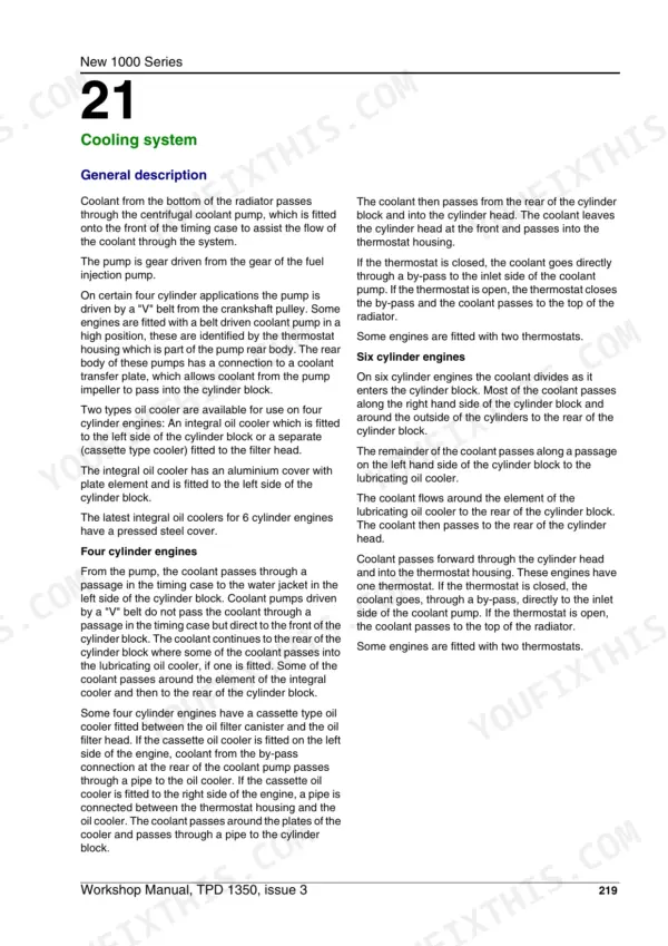
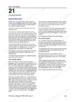
| Engine: Cooling, Flywheel, Electrical and Auxiliary Equipment | 296-381 | Cooling System and Fan Belt Tension, Flywheel and Housing, Electrical Equipment, Auxiliary Equipment, Special Tools |
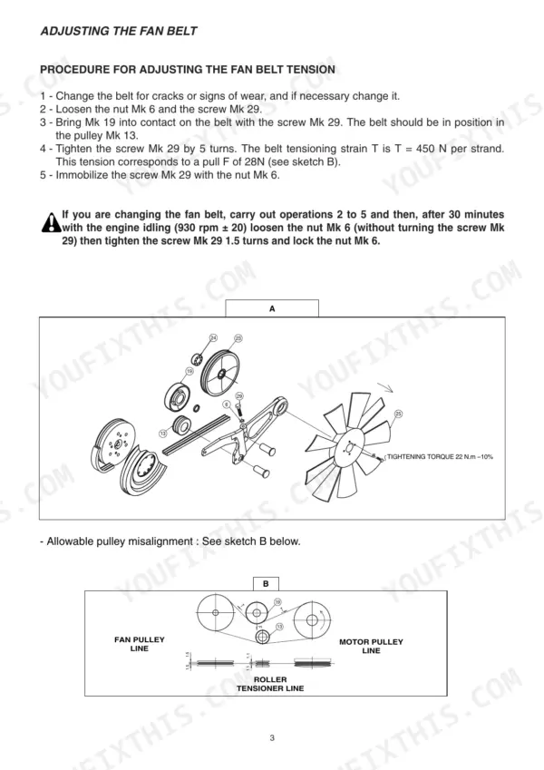
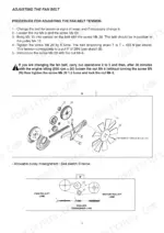
| Engine Cooling System (Manitou) | 382-387 | Adjusting the Fan Belt |
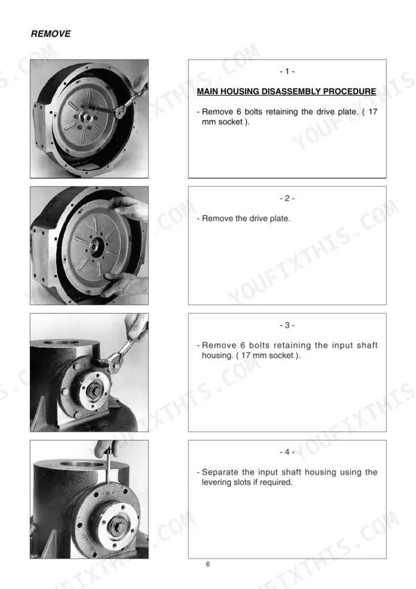
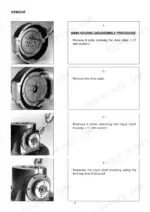
| Bevel Gear (Angle Gear-Box) | 388-413 | Bevel Gear Disassembly and Reassembly, Input and Output Shafts, Bearing Preload, Flange Torques |
| Gear Box / Converter: Compact Shuttle Transmission | 414-473 | Line of Force Forward and Backward, Hydraulic Circuit, Disassembly and Reassembly, Clutch Pressure Checks, Troubleshooting |
| Gear Box with Electrical Control Valve | 474-527 | Electrical Control Valve Details, Converter Relief and Pressure Regulator Valves, Lubrication Pressure Test Point, Dis-Assembly and Re-Assembly, Test Procedure |
| Axle Assembly | 528-695 | Disassembly and Reassembly of the Axle Assembly, Hub Reducers, Differential |
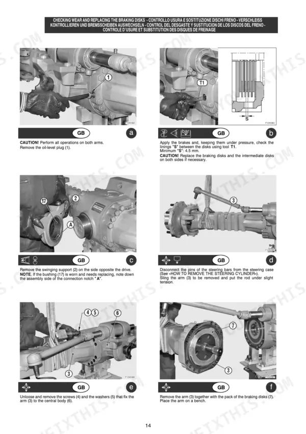
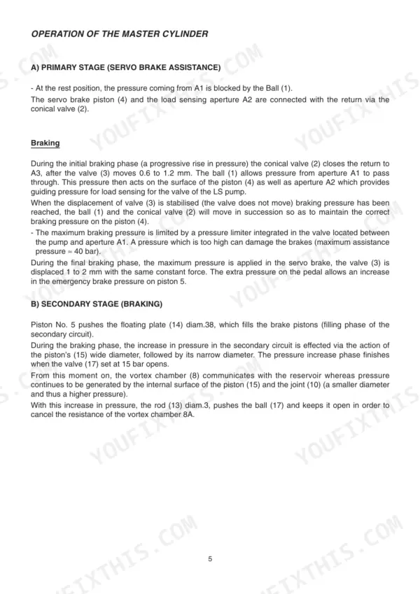
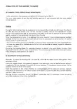
| Brake | 696-707 | Operation of the Brake System, Brake Troubleshooting and Purge |
| Telescopic Boom (Jib) | 708-803 | Jib Disassembly and Reassembly, Telescope Cylinders Removal |
| Hydraulic Cylinders | 804-839 | Cylinder Disassembly and Reassembly per Model, Seals, Tightening Torques |
| Hydraulic Pressures | 840-847 | Checking and Adjustment of the Main Pressure Relief Valve, Steering Pressure, Values Chart per Model |
| Hydraulic Diagrams | 848-957 | Hydraulic Diagram and Valve Bank per Model, ML 632/635 to MT 1637 SLT ORH, Balancing and Overcenter Valves |
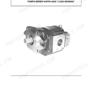
| Valve Test Stand and LS Pump | 958-981 | Test Stand Valves Adjustment, LS Pump Operation |
| Fuse and Relay Plate | 982-989 | Diagram for Fuses and Relay Plate |
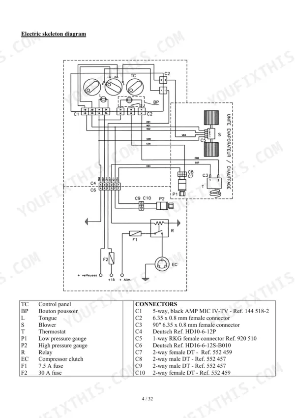
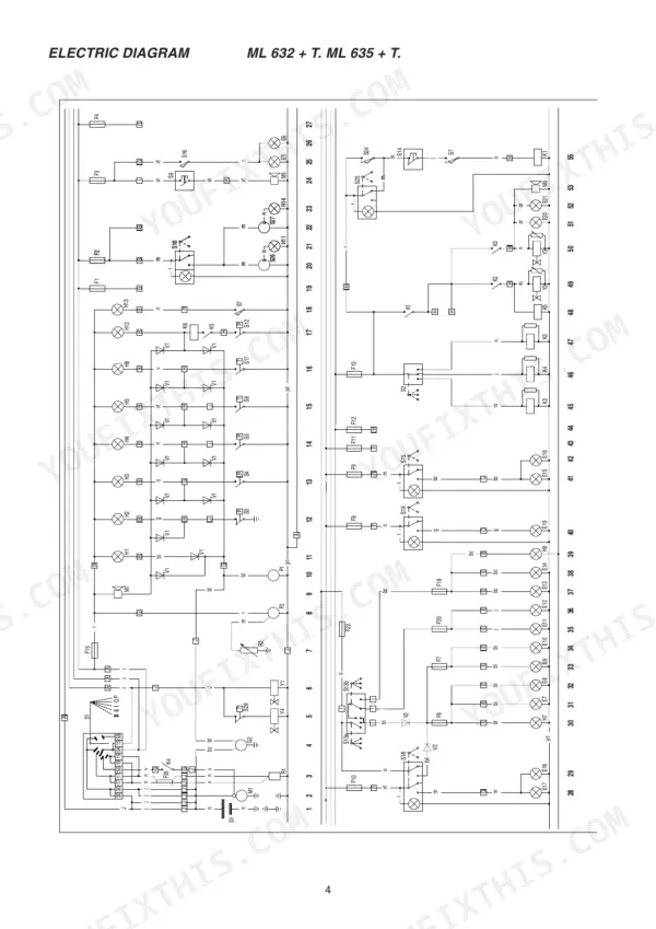
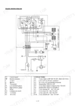
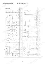
| Electric Diagrams | 990-1054 | Principle Electric Circuit and Legend per Model, Colour Coding, Nacelle ORH Platform Controls |
| Longitudinal Stability Alarm | 1055-1063 | Operating and Setting of the Longitudinal Stability Alarm, Strain Gauge Inspection |
| Driver Cab and Air-Conditioning | 1064-1103 | Air-Conditioning Operation and Adjustment |
Quick Reference Specifications
| Specification | Value | Page |
|---|---|---|
| All Models | ||
| Engine Type | PERKINS 1004.42 AR 81026 (ML 632 Série 2, ML 635 Série 2) / PERKINS 1004.40T AK 80920 (ML 632 Turbo Série 2, ML 635 Turbo Série 2) / PERKINS 1004.40TW AM 80922 (MT 835 - 120 LS Série 2) / PERKINS 1004.42 AR 81026 or AR 81334 (MT 845 to MT 1637 SL Série 2) / PERKINS 1004.40T AK 80920 or AK 81298 or AK 81336 (MT 845 to MT 1637 SL Turbo Série 2 + Turbo MONO-ULTRA) | p. 7 |
| Power ISO 3046-1 | 76 cv / 56 kw (MOTEUR 1004.42) / 99 cv / 73 kw (MOTEUR 1004.40T) / 119 cv / 87,5 kw (MT 835 - 120 LS Série 2) | p. 7 |
| ML 632 Série 2, ML 635 Série 2 | ||
| Engine Type | PERKINS 1004.42 AR 81026 | p. 7 |
| ML 632 Turbo Série 2, ML 635 Turbo Série 2 | ||
| Engine Type | PERKINS 1004.40T AK 80920 | p. 7 |
| MT 835 - 120 LS Série 2 | ||
| Engine Type | PERKINS 1004.40TW AM 80922 | p. 19 |
| Power ISO 3046-1 | 119 cv / 87,5 kw | p. 19 |
| MT 845 to MT 1637 SL Série 2 | ||
| Engine Type | PERKINS 1004.42 AR 81026 or AR 81334 | p. 31 |
| MT 845 to MT 1637 SL Turbo Série 2 + Turbo MONO-ULTRA | ||
| Engine Type | PERKINS 1004.40T AK 80920 or AK 81298 or AK 81336 | p. 31 |
| MOTEUR 1004.42 | ||
| Power ISO 3046-1 | 76 cv / 56 kw | p. 7 |
| MOTEUR 1004.40T | ||
| Power ISO 3046-1 | 99 cv / 73 kw | p. 7 |
| ML 632 / ML 635 Série 2 | ||
| Clearance of rocker valve (Cold) | Inlet 0,20 mm / Exhaust 0,45 mm | p. 7 |
| ML 632 Série 2 | ||
| Lifting, tilting, attachment circuit pressure | 260 Bar | p. 9 |
| Steering circuit pressure | 140 Bar | p. 9 |
| Compact shuttle transmission | ||
| Forward / reverse gear clutch pressure | 195-210 P.S.I. (14 ± 0.5 bar) | p. 430 |
Manitou ML 632, ML 635, MT 940 L, MT 1337 SL, MT 1740 SL Common Problems This Manual Covers
Machine stops moving under load, or the transmission slips and overheats after hard work
Start with the clutch pressure checks in the Compact Shuttle Transmission chapter and compare your readings with the printed values. Low pressure on one direction points at that clutch pack or its seals. Then follow the disassembly and reassembly steps. On electrically shifted boxes, check the converter relief and pressure regulator valves first.
Manual Section: Gear Box / Converter: Compact Shuttle Transmission; Gear Box with Electrical Control Valve p. 430Lift, tilt or steering weak and erratic
Put a gauge on the circuit and compare your reading with the Hydraulic Pressures chart for your model. On the ML 632 and ML 635 that means 260 bar for lift and 140 bar for steering. Change the 10 micron return and 100 micron suction filters first. If the pump still reads low, see the LS pump operation pages.
Manual Section: Hydraulic Pressures; Valve Test Stand and LS Pump p. 843Boom creeps down or telescopes unevenly
Find the balancing and overcenter valves for your model in the Hydraulic Diagrams chapter and test them before blaming the cylinder. If a cylinder is bypassing, the Cylinders Disassembly pages in the Hydraulic group cover the seals, reassembly and tightening torques. The Telescopic Boom chapter shows how to remove the telescope cylinders.
Manual Section: Hydraulic Diagrams; Hydraulic Cylinders; Telescopic Boom (Jib) p. 950Work lights, controls or other electrics drop out intermittently
Start at the Fuse and Relay Plate diagram and confirm each fuse and relay position. Then trace the faulty circuit on the Electric Diagrams for your model using the legend and wire colour coding. Check the harness connectors and switches along the run. Units with an ORH nacelle have their own platform control diagrams.
Manual Section: Fuse and Relay Plate; Electric Diagrams p. 984Frequently Asked Questions
My telehandler revs but loses drive under load. Does this manual cover the shuttle transmission?
Yes. The Compact Shuttle Transmission section covers the forward and backward line of force, the hydraulic circuit, clutch pressure checks and troubleshooting. There is also a separate chapter for the gearbox with electrical control valve. It covers the converter relief valve, the pressure regulator valve and the lubrication pressure test point. Check pressures before you pull the box, because a low reading points you at the right clutch pack. p. 430
What hydraulic pressures should an ML 632 or ML 635 Série 2 run?
The characteristics pages list 260 bar for the lifting, tilting and attachment circuit, 140 bar for steering and 40 bar for braking. They also give 98 L/mn maximum unladen flow from a 41 cm³ gear pump with flow divider. The Hydraulic Pressures chapter shows how to check and adjust the main relief valve and steering pressure. It includes a values chart for every other model. p. 9
Which Perkins engine is in my machine, and how do the versions differ?
The naturally aspirated ML 632 and ML 635 use the 1004.42, with 4233 cm³, a 103 mm bore and 76 cv under ISO 3046-1. The Turbo versions use the 1004.40T, with 3990 cm³, a 100 mm bore and 99 cv. The MT 835-120 LS runs a 3990 cm³ turbo engine rated at 119 cv. Both engines share the 127 mm stroke. p. 7
What are the valve clearances and idle speed on the 1004 engines?
Set the rockers cold at 0,20 mm inlet and 0,45 mm exhaust. Firing order is 1.3.4.2. Slow idle unladen is 930 rpm +20, and nominal loaded speed is 2200 rpm. The bound-in Perkins manual covers the valve tip clearance procedure in its cylinder head chapter. Getting the lash right on the first try saves you a second trip under the cover. p. 112
The longitudinal stability alarm keeps going off or never sounds. Is setting it covered?
It has its own chapter. It explains how the alarm works, how to set it and how to inspect the strain gauge. Check the gauge and its wiring before you assume the alarm unit has failed. A damaged gauge or a poor connection gives false readings in both directions. p. 1059


Reviews
There are no reviews yet.