
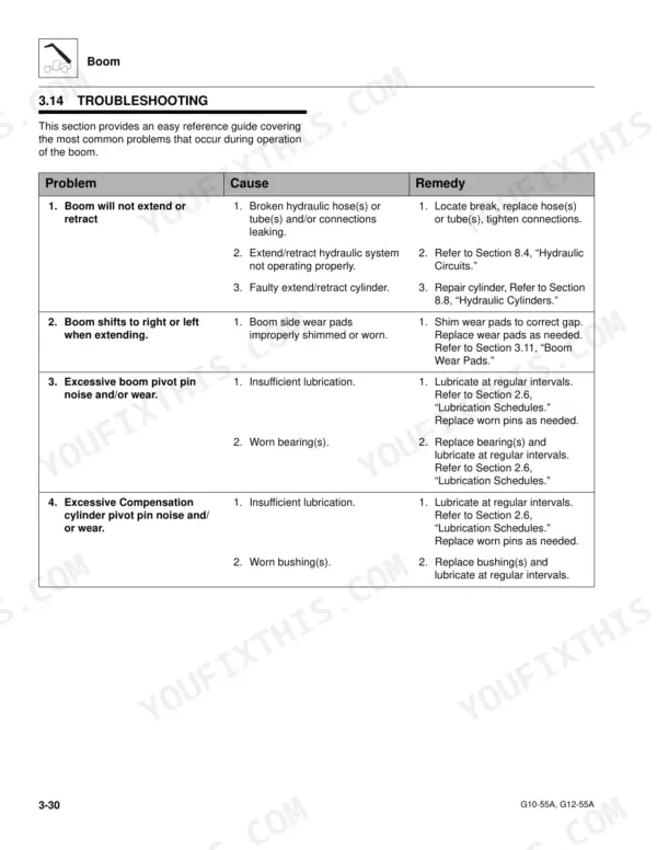
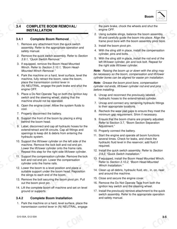
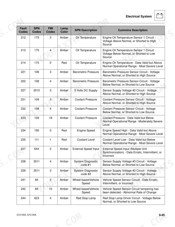
Rebuilding a boom or tracing a hydraulic fault goes faster when all 200 pages of the JLG G10-55A, G12-55A service manual PDF (OEM 3126019) sit open on your bench, covering both telehandlers from safety practices through the electrical schematics that close the book. Those schematics take up roughly the last quarter, with circuit breakdowns for the engine start, wiper motor, cab heater, dash switches, and Cummins SAE fault codes. Boom work runs just as deep: section removal, extend and retract chain replacement, wear pad service, and separation adjustment, plus dedicated chapters for the John Deere, Perkins, and Cummins engine options. Set main circuit pressure between 3600 and 3650 psi, then torque the lug nuts to 350 to 400 lb-ft, straight from JLG's own tables. A dead start circuit with no schematic eats your morning. Bookmarks and a live text layer put you on the right circuit in seconds.
What's Inside This JLG G10-55A, G12-55A Manual
| System | Pages | Key Topics |
|---|---|---|
| Safety Practices | 9-12 | Introduction, Disclaimer, Operation & Safety Manual, Do Not Operate Tags, Safety Information, Safety Instructions, Safety Decals |
| General Information and Specifications | 13-34 | Replacement Parts and Warranty Information, Torque Charts, Specifications, Fluid and Lubricant Capacities, Service and Maintenance Schedules, Lubrication Schedules |
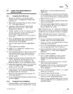
| Boom | 35-66 | Boom System Component Terminology, Boom System - Four Section, Boom Assembly Maintenance, Complete Boom Removal/Installation, Boom Section Removal/Installation |
| Cab and Covers | 67-76 | Operator’s Cab and Covers Component Terminology, Operator’s Cab, Cab Components, Cab Removal, Cab Installation |
| Axles, Drive Shafts, Wheels and Tires | 77-88 | Axle, Drive Shaft and Wheel Component Terminology, Axle Assemblies, Drive Shafts, Wheels and Tires, Brakes, Towing a Disabled Machine |
| Transmission | 89-98 | Transmission Assembly Component Terminology, Transmission Serial Number, Transmission Specifications and Maintenance Information, Transmission Replacement |
| Engine | 99-116 | Introduction - John Deere, Introduction - Perkins, Introduction - Cummins, Engine Cooling System, Engine Electrical System, Fuel System, Engine Exhaust System, Air Cleaner Assembly |
| Hydraulic System | 117-142 | Hydraulic Component Terminology, Safety Information, Hydraulic Pressure Diagnosis, Hydraulic Circuits, Hydraulic Reservoir, Implement Pump, Control Valves, Hydraulic Cylinders |
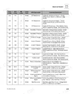
| Electrical System | 143-200 | Electrical Component Terminology, Specifications, Safety Information, Fuses and Relays, Electrical System Schematics |
Quick Reference Specifications
| Specification | Value | Page |
|---|---|---|
| All Models | ||
| Steering wheel nut torque | 29-34 lb-ft (39-46 Nm) | p. 70 |
| Wheel lug nut torque | 350-400 lb-ft (475-542 Nm) | p. 87 |
| Main circuit pressure (Before S/N 0160037877) | 3600-3650 psi (248-252 Bar) | p. 122 |
| Pilot circuit pressure (Before S/N 0160037877) | 500-550 psi (34-38 Bar) | p. 122 |
| Lift/Lower Cylinder Head Torque (G12-55A - Before S/N 0160033659 excluding 0160033452) | 550-600 lb-ft (745-813 Nm) | p. 140 |
| Lift/Lower Cylinder Nut Torque (G12-55A - Before S/N 0160033659 excluding 0160033452) | 2850-2900 lb-ft (3864-3932 Nm) | p. 140 |
| Perkins Engine Crankcase Oil Capacity | 7 quarts | p. 27 |
| Cummins Engine Crankcase Oil Capacity | 13.5 quarts | p. 27 |
| Hydraulic Reservoir Capacity | 38 gallons | p. 28 |
| Transmission Capacity with Filter Change | 4 gallons | p. 28 |
| G10-55A | ||
| John Deere (G10-55A) Engine Crankcase Oil Capacity | 14.3 quarts | p. 27 |
| G12-55A | ||
| John Deere (G12-55A) Engine Crankcase Oil Capacity | 15.8 quarts | p. 27 |
JLG G10-55A, G12-55A Common Problems This Manual Covers
JLG G10-55A won't move forward or reverse, dash shows CAN bus fault, gauges cutting out
Check battery terminals and chassis grounds first; a weak 12 volt supply drops the CAN network before anything else fails. Trace the data lines between the dash cluster and the transmission controller against the electrical system schematics in Section 9, which starts on page 143. Clean and reseat connectors, then test drive. If the fault returns, check the shifter controller connections.
Manual Section: Electrical System p. 143Transmission slipping under load with low clutch pressure warning, drive lags on grades
Check transmission oil level hot at idle before condemning anything; low oil is the usual culprit. Drain and refill with 4 gallons when changing the filter, and torque the new filter to 20-25 lb-ft (27-34 Nm). If clutch pressure stays low with correct oil, work through the transmission chapter beginning on page 89.
Manual Section: Transmission p. 89All hydraulic functions slow and weak, boom lift and extend lose power when warm
Test main circuit pressure at port P1 with tilt bottomed: spec is 3600-3650 psi (248-252 Bar) on machines before S/N 0160037877, listed on page 122 (later machines use page 123). Check standby pressure of 750-775 psi with no function active. Low readings with a full 38 gallon reservoir point to a worn variable displacement pump.
Manual Section: Hydraulic Pressure Diagnosis p. 122Boom drifts down under load, lift cylinder weeps oil past the rod seal
Inspect the rod for scoring or chrome damage first; a scored rod destroys new seals fast. Rebuild with the correct seal kit, then torque the lift cylinder head to the spec for your serial number on page 140, 550-600 lb-ft (745-813 Nm) on machines before S/N 0160033659. Cycle the boom and recheck for drift.
Manual Section: Hydraulic System p. 140Grinding or clunking noise from the transmission when shifting or pulling a load
Shut it down and check the transmission oil level immediately; grinding usually means the oil is running low. Check the transfer case too, it only holds 1.5 quarts and drains fast past a leaking seal. If oil is good, inspect drive shaft U-joints for play, covered in the axle chapter starting on page 77.
Manual Section: Transmission p. 89Frequently Asked Questions
What are the torque specifications for the wheel lug nuts on the G10-55A and G12-55A?
The standard wheel lug nut torque for the G10-55A and G12-55A is 350-400 lb-ft (475-542 Nm). p. 26
What does fault code 148 mean on a JLG G10-55A?
Fault code 148 indicates an issue with the Accelerator Pedal or Lever Position Sensor Circuit, specifically an abnormal frequency, pulse width, or period. p. 186
What is the engine oil capacity for the John Deere engine in a G10-55A?
The engine oil capacity with a filter change for the John Deere engine in a G10-55A is 14.3 quarts (13,5 liters). p. 27
What is the correct torque for the transmission mounting bolts on the G10-55A and G12-55A?
The transmission mounting bolts should be torqued to 125-140 lb-ft (170-190 Nm). p. 93
How often should the boom chains be inspected on the G10-55A and G12-55A?
Under normal operating conditions, the boom chains should be inspected every 250 hours of operation. Additionally, the retract chains need to be exposed and inspected every 1000 hours of operation. p. 59
Is this JLG G10-55A Service Manual a digital download?
Instant PDF download. You get the full 200-page searchable Service Manual immediately after payment. Open it on your laptop, tablet, or phone right in the shop.
Does this JLG G10-55A manual allow printing?
Yes. Print the pages you need for the job in your own shop, and bin them when they get greasy.


Reviews
There are no reviews yet.