
SMART HANDLING is where a 2706 / KT276 repair usually stalls. The overload limiter ties the load sensor, rotary angle sensor, safe load indicator and lowering control together, and the error tables include a not-calibrated code for the safe load indicator. This handbook covers that system from both sides, hydraulic and electrical, and lists the error codes it throws.
It also covers the Kohler KDI 2504TCR engine and the hydrostatic drive, with test protocols for the 20 km/h and 30 km/h versions. Brakes, steering modes, the third circuit, wiring diagrams, controller inputs and outputs, heating and central lubrication are in there too. It applies to machine model 418-02 from serial no. 418 02 0011.
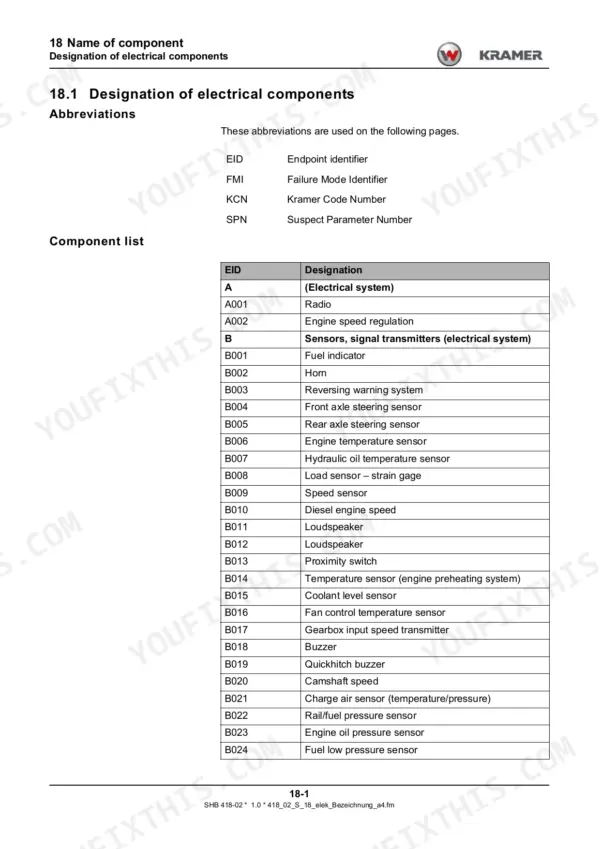
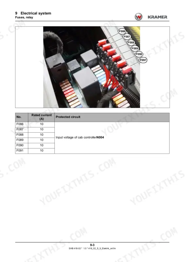
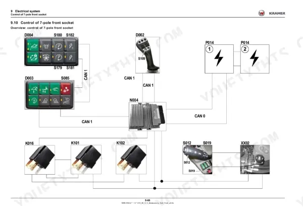
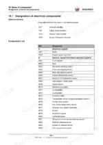
Component names and installation positions help locate each sensor, valve and controller named in the diagrams and error tables.
What's Inside This Kramer 2706, KT276 Manual
| System | Pages | Key Topics |
|---|---|---|
| Introduction | 1-25 | Manual Use, Symbols and Abbreviations, Repair Instructions, Tools, Tightening Torques, Safety |
| Engine | 26-79 | Engine Specifications, Lubrication, Fuel Injection, Intake and Exhaust, Engine Electronics, Exhaust After-Treatment, Starting and Monitoring |
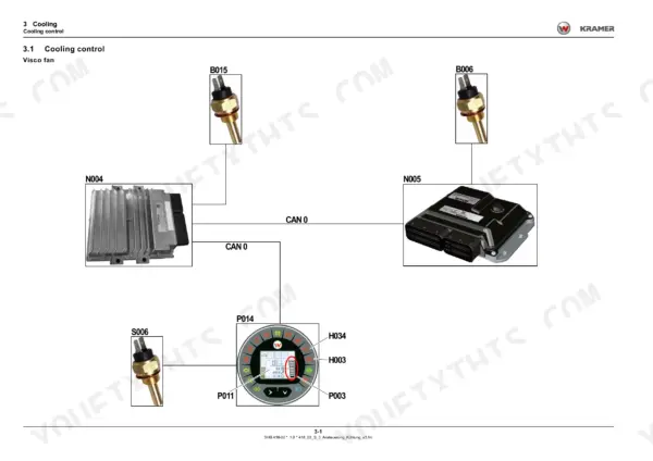
| Cooling | 80-92 | Cooling Control, Temperature Sensors, Coolant Level Sensor, Oil Temperature Switch, Reversing Fan, Fan Solenoid Valves |
| Power Train | 93-129 | Hydrostatic Assemblies, Test Ports, Drive Test Protocols, Pressure Adjustment, Speed Adjustment, Troubleshooting, Drive Control |
| Brakes | 130-163 | Service Brake, Parking Brake, Brake Valves, Test Protocols, Brake Control, Hydraulic Trailer Brake, Trailer Coupling Safety |
| Steering | 164-192 | Steering Modes, Synchronisation, Test Protocols, Cylinder Adjustment, Steering Stops, Orbitrol, Steering Valves |
| Hydraulics - Work Hydraulics and Components | 193-244 | Functional Characteristics, Control Valve Sections, Accumulators, Tanks and Filters, Test Protocols, Pressure Adjustment, Component Torques |
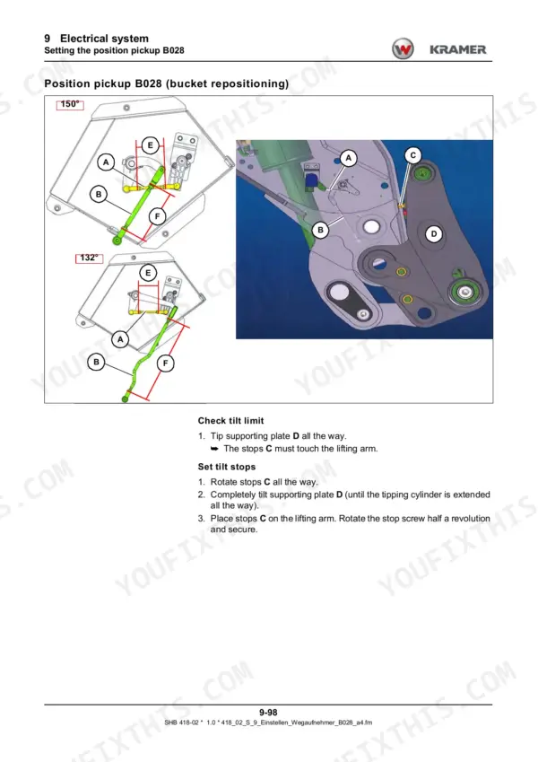
| Hydraulics - Boom and Load Stabiliser | 245-329 | Boom Raising and Lowering, Load Stabiliser, Hose Burst Valves, Telescopic Cylinder, Tipping Cylinder Lock, Bucket Repositioning |
| Hydraulics - Third Circuit and Rear Hydraulics | 330-418 | Third Control Circuit, Reversing Valve, Rear Additional Circuit, Tipper Control, Auto Hitch, Sensor Plate Adjustment |
| Hydraulics - Overload Limiter (SMART Handling) | 419-453 | Overload Limiter, Load Sensor, Safe Load Indicator, Lifting Restrictions, Lowering Control, Hydraulic and Electrical Interfaces |
| Hydraulics - Hydraulic Diagrams | 454-485 | Total Hydraulic Circuits, Diagram Legends, Reversible Third Circuit, Rear Additional Circuits, Auto Hitch and Tipper, Trailer Brake |
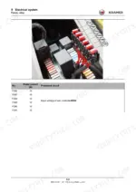
| Electrical System - Fuses, Relays and Controllers | 486-526 | Fuses, Relays, CAN Signals, Traction Controller Inputs and Outputs, Cab Controller, Diesel Engine Controller |
| Electrical System - Telematics and Sockets | 527-566 | Telematics, Drive Interlock, 14-Pole Front Socket, 7-Pole Front Socket, 7-Pole Rear Socket, Attachment Control Relays |
| Electrical System - Joystick and Load Indicator | 567-596 | Joystick, Safe Load Indicator, Load Indicator Calibration, Load Sensor, Rotary Angle Sensor, Indicating Instrument, Camera Option |
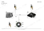
| Electrical System - Wiring Diagrams | 597-840 | Engine Wiring, Traction Electronics, CAN Diagnostics, Power Distribution, Lighting, Attachment Circuits, Component Lists |
| Heating and Air Conditioning | 841-848 | Cab Heating, Blower, Heat Exchanger, Recirculated-Air Filter, Air-Conditioning Pressure Switch, Fan Pump and Motor |
| Component Names | 849-866 | Component Designations, Sensors, Control Units, Switches, Connectors, Relays, Solenoid Valves |
| Installation Positions | 867-908 | Hydraulic Component Locations, Electrical Component Locations, Valves, Sensors, Controllers, Connectors |
| Error Codes | 909-966 | Drive Interlock Codes, Safe Load Indicator Codes, Cab Electronics Codes, Traction Electronics Codes, Diesel Engine Codes |
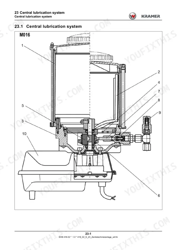
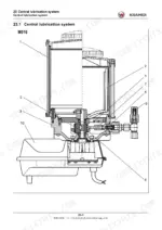
| Central Lubrication System | 967-978 | Lubrication Pump, Electronic Control, Timing Settings, Pressure Limiting Valve, Progressive Distributor, Lubrication Points |
Quick Reference Specifications
| Specification | Value | Page |
|---|---|---|
| Engine | Kohler KDI 2504TCR NA V-Belt | p. 27 |
| Engine power (ISO14396) | 55.4 kW (74,3 hp) | p. 27 |
| Engine max. torque | 300 Nm (221.3 ft.lb) | p. 27 |
| Max. engine speed without load | approx. 2600 U/min (rpm) | p. 27 |
| Engine idling speed | approx. 950 U/min (rpm) | p. 27 |
| Engine oil working pressure | 4 bar (58.01 psi) | p. 36 |
| Common rail fuel pressure | 2000 bar (29007.55 psi) | p. 46 |
| Drive boost pressure (test protocol, 20 km/h) | 30-32 bar (435.10-464.10 psi) | p. 102 |
| Drive high pressure (test protocol, 20 km/h) | 460-490 bar (6671.74-7106.85 psi) | p. 102 |
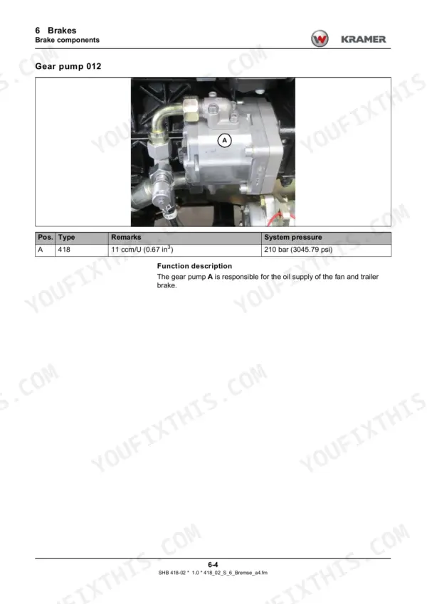
| Trailer brake valve 140 (France) | 120 - 140 bar (1740.45 - 2030.53 psi) | p. 133 |
| Steering pressure at max. engine speed | 160-190 bar (2320.6-2755.72 psi) | p. 170 |
| 3rd control circuit section 067 flow | 80 l/min (21.10 US gpm) | p. 206 |
| Secondary valve 069, raise lift cylinder | 270-290 bar (3916-4206 psi) | p. 206 |
| Secondary valve 071, push-out ram extend | 190 - 210 bar (2755 - 3045 psi) | p. 206 |
| Pilot control pressure accumulator 077 gas filling | 10 bar (145 psi) | p. 211 |
| Load stabiliser pressure relief valve 079 | 280 bar (4061 psi) | p. 214 |
| Hydraulic oil tank drain plug torque | 35 Nm (25.8 ft.lb) | p. 231 |
| Hydraulic tank suction filter torque | 50 Nm (36.9 ft.lb) | p. 233 |
| Work hydraulics pressure at max. engine speed | 250-260 bar (3625.94-3770.98 psi) | p. 235 |
| Central lubrication working pressure | 280 bar (4061.1 psi) | p. 972 |
Kramer 2706, KT276 Common Problems This Manual Covers
Display shows 606 P006 Safe load indicator not calibrated
The Error Codes chapter lists 606 (SPN 516606, FMI 13) as not calibrated, and the action is to calibrate. Electrical System - Joystick and Load Indicator walks through load indicator calibration and checks on the load sensor and rotary angle sensor.
Manual Section: Error codes - Error codes for safe load indicator P006 p. 911Hydrostatic drive pressures need checking
Power Train gives the test ports and drive test protocols. On the 20 km/h version, boost should read 30-32 bar (435.10-464.10 psi) and high pressure 460-490 bar (6671.74-7106.85 psi). Pressure adjustment, speed adjustment and troubleshooting steps follow.
Manual Section: Power train - Test protocol model 418-02 (20 km/h) p. 102Engine fault 094 from diesel engine electronics N005, fuel pressure sensor
Error Codes lists 094 (SPN 94, FMI 6) as current too high or a short to machine ground. The listed actions are a visual inspection of the engine wiring harness, change ignition, and contact manufacturer. Electrical System - Wiring Diagrams has the engine wiring for tracing the sensor circuit.
Manual Section: Error codes - Error code for diesel engine electronics N005 p. 951Drive electronics N001 logs 409 Gearbox speed sensor fault
Error Codes lists 409 (SPN 516409, FMI 12) as a short or open circuit in a signal line. Check the line from sensor B009 PIN 2 and PIN 3 to control unit N001 connector CC1 PIN 5 and CC2 PIN 4. Installation Positions shows where the sensor and controller sit.
Manual Section: Error codes - Error code drive electronics N001 p. 949Frequently Asked Questions
Which Kramer telehandlers does this System Handbook cover?
It covers the Kramer 2706 and KT276, machine model 418-02, from serial no. 418 02 0011. It is document number 1000363122, version 1.0, in English. Drive test protocols are given for both the 20 km/h (12.4 mph) and 30 km/h (18.6 mph) versions. p. 1
What engine does the Kramer 2706 / KT276 use and what are its power and torque?
It runs a Kohler KDI 2504TCR NA V-Belt, also listed as LRC1. Output is 55.4 kW (74,3 hp) per ISO14396 at 2300 rpm. Max. torque is 300 Nm (221.3 ft.lb) at 1500 rpm. Idle sits around 950 rpm and no-load max. is about 2600 rpm. p. 27
What work hydraulics test pressure and third circuit flow does the Kramer 2706 / KT276 handbook give?
The work hydraulics test value at max. engine speed is 250-260 bar (3625.94-3770.98 psi). Third control circuit section 067 is rated at 80 l/min (21.10 US gpm). Steering should read 160-190 bar (2320.6-2755.72 psi) at max. engine speed. p. 235
What load stabiliser and pilot accumulator settings are listed for the Kramer 2706 / KT276?
Pressure relief valve 079 on the hose burst valve with load stabiliser is set to 280 bar (4061 psi). Pilot control pressure accumulator 077 takes a 10 bar (145 psi) gas filling. Secondary valve 069, raise lift cylinder, is 270-290 bar (3916-4206 psi). p. 214
Does the Kramer 2706 / KT276 handbook include wiring diagrams, hydraulic diagrams and error codes?
Yes. The hydraulic diagrams come with legends and cover the total circuit, third circuit, rear additional circuit, auto hitch and tipper, and trailer brake. Wiring diagrams cover the diesel engine, travelling drive, CAN and diagnostics, and the safe load indicator. The error code chapter lists codes with alarm text and actions, for example 606 P006 Safe load indicator, not calibrated: calibrate. p. 909


![International 444 Tractor, International 444 Tractor... [list], gearshift pattern diagram, driving and starting procedures.](https://youfixthis.com/wp-content/uploads/2026/06/international-444-tractor-tractor-operator-manual-1082661r2-operations-11-64x83.webp)
Reviews
There are no reviews yet.