
This is Kramer System Manual 1000447714 for the 4507/KT457, 5007/KT507, 5507/KT557, 4209/KT429 and 5509/KT559 telehandlers. It covers the hydrostatic travel drive with the H1P pump and both the ICVD and P370 gearboxes. Test reports cover boost pressure, high pressure, cardan shaft speed and engine droop.
It also covers the Deutz TCD 3.6 and TCD 4.1 engines, DOC, DPF and SCR aftertreatment, the brakes, the four steering modes and the work hydraulics. CAN controllers, the safe load indicator and the cameras are covered as well. It includes full hydraulic circuit diagrams and electrical wiring diagrams.
What's Inside This Kramer 4209–5509, KT429–KT559 Manual
| System | Pages | Key Topics |
|---|---|---|
| Introduction, Safety and Tightening Torques | 1-27 | Use of the System Manual, Required Tools and Gauges, Safety Instructions, High-Pressure Fluid and Hose Replacement, Jacking and Parking, Symbols and Abbreviations, Cable Colour Codes, Tightening Torques, Hydraulic Screw Connections |
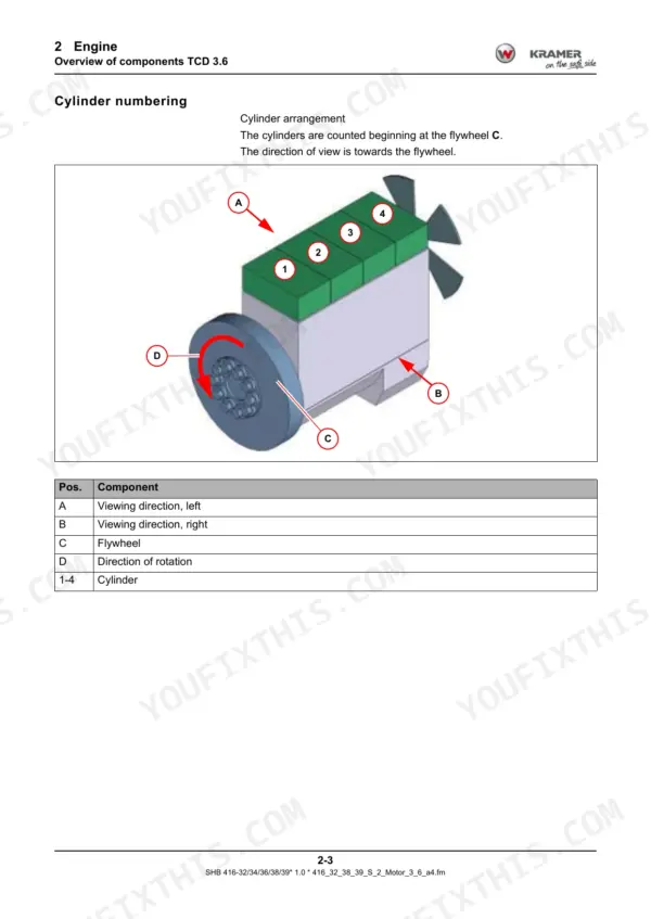
| Engine: Deutz TCD 3.6 | 28-60 | Technical Data, Type Plates, Lube Oil Circuit, Fuel System, Injectors, High-Pressure Pump, Rail Pressure Relief Valve, Cooling and Thermostat, Turbocharging, EGR, Electric Components |
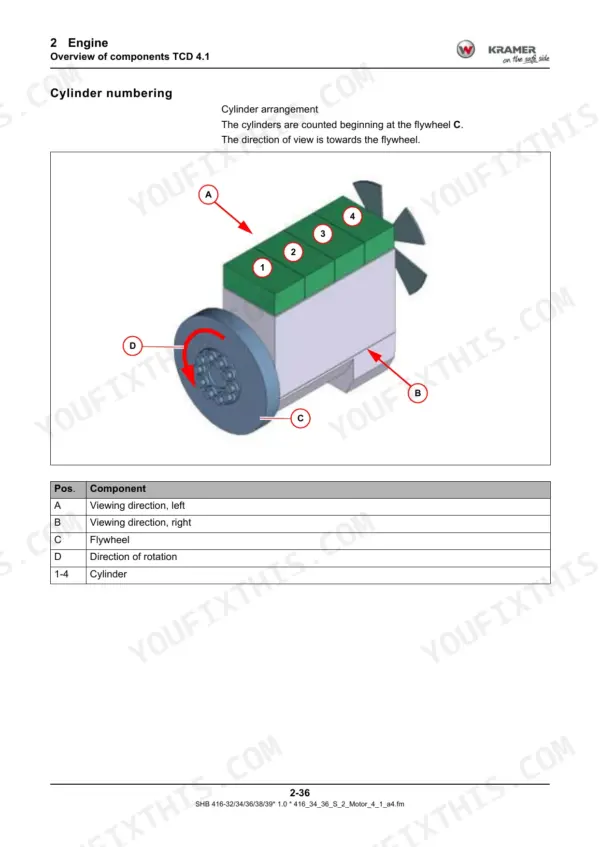
| Engine: Deutz TCD 4.1 | 61-91 | Technical Data, Type Labels, Lube Oil System, Fuel System, Metering Unit, High-Pressure Pump, Cooling Circuit, Thermostat Check, Turbocharging, EGR, Electric Components |
| Exhaust-Gas Aftertreatment | 92-121 | Emission Stages, SCR Catalytic Converter, DOC and Particulate Filter, Urea Metering Unit, Differential Pressure and Temperature Sensors, NOx Sensors, Urea Fill Level, Tank Heater |
| Engine Starting, Monitoring and EAT Control | 122-132 | Starting with Drive Interlock, Engine Monitoring, Oil Pressure Indicator, Battery Charge Control, Preheating, Air Filter Clogging, EAT Control and Heating Circuit |
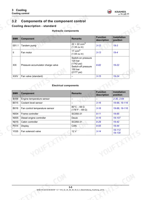
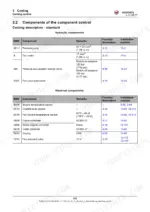
| Cooling | 133-154 | Cooling Control, Reversing Fan, Tandem Pump, Fan Motor, Reversing Valve, Fan Valve, Coolant Level Sensor, Engine Speed Check, Fan Speed Test and Adjustment |
| Travel Drive: Control and Components | 155-171 | Drive Control, Variable Displacement Pump, Boost Pressure, Travel Speeds Snail, Tortoise and Hare, Speed Sensor, Proportional Valves, Direction Identification Valve, PCOR Valve |
| Travel Drive: H1P Pump with ICVD Gearbox | 172-213 | ICVD Drive System, Gearbox Swivel, Test Reports, Test Ports, Boost Pressure, Starting Speed, Pressure Cut-Off, High Pressure, Cardan Shaft Speed, Engine Droop, Error Descriptions |
| Travel Drive: H1P Pump with P370 Gearbox | 214-254 | P370 Drive System, Test Reports, Boost Pressure, Starting Speed, High Pressure, Cardan Shaft Speed, Engine Droop, Error Descriptions, PCOR and Speed Valves |
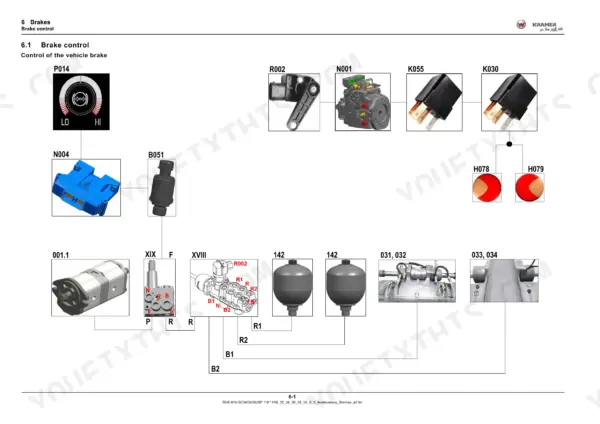
| Brakes | 255-335 | Brake Control, Hydraulic and Compressed-Air Trailer Brake, Pressure Accumulators and Charge Valve, Brake Valve, Compressor and Air Reservoir, Trailer Control Valves, Brake Test Logs |
| Steering System | 336-358 | Steering Function, Double Gear Pump, Hydrostatic Steering Unit, Steering Mode Valve, Steering Sensors, Four Steering Modes, Steering Pressure Switch, Steering Pressure Check |
| Hydraulics: Control Circuits | 359-403 | Lifting Cylinder and Load Stabilizer, Overload Control, Tilt Ram, Bucket Repositioning, 3rd Control Circuit, Tipper and Auto-Hitch, Additional Control Circuits, Oscillating-Axle Interlock |
| Hydraulics: Components | 404-443 | Tandem Pump, Filters, Accumulators, Hose Burst Valves, Quickhitch Lock, Changeover and Relief Valves, Variable Displacement Pump, Control Unit and Secondary Valves, Hydraulic Tank |
| Hydraulics: Check and Adjust | 444-458 | Test Report, Engine Speed Check, Circuit Pressure, Working Pressure, Pump Pressure Regulator, LS Pressure, Pilot Control Pressure, Secondary Valve Checks |
| Hydraulic Diagrams | 459-476 | Work Hydraulics Diagram, Control Unit Legend, ICVD and P370 Drive Diagrams, Brake Circuit Diagram, Steering Circuit Diagram, Legends |
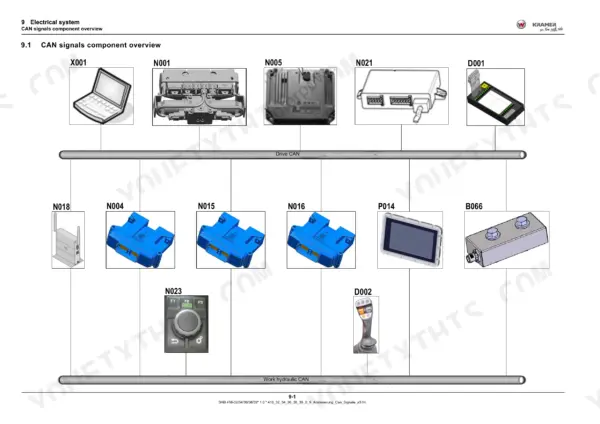
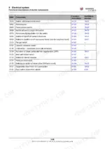
| Electrical System: Controllers and Fuses | 477-543 | CAN Signals, Traction Electronics, Frame, Engine and Cab Controllers, Telematics, Drive Interlock, Steering Electronics, Joystick, Display, Fuses and Relays |
| Safe Load Indicator, Calibration and Cameras | 544-571 | Safe Load Indicator, Calibration, Travel Sensor Basic Setting, Front Camera Setup and Display Modes, Rear Camera |
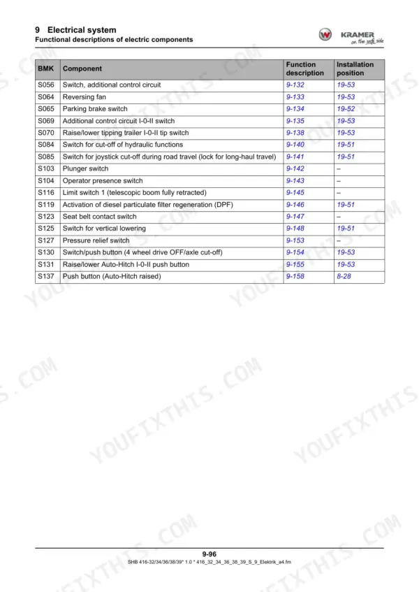
| Electrical Components: Functional Descriptions | 572-635 | Sensors, Buzzer, Relays, Accelerator Pedal, Angle Sensor, Switches, Plug Pin Assignments, Autohitch, Load Stabilizer, DPF Regeneration |
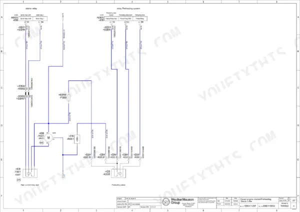
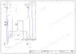
| Electrical Wiring Diagrams | 636-870 | Circuit Diagrams for Deutz 3.6 and Deutz 4.1 Machines, Contents Sheets, Lights, Brake, CAN, Engine Starter and Preheating, Eat, Injectors, Alternator, Item Register |
| Heating and Air Conditioning | 871-888 | Heating and a/C Circuit, Safety, R134a Charge, Compressor, Blower, Heating Switch, Dryer, Evaporator, Condenser |
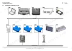
| Installation Positions | 889-1021 | Hydraulics, Cab Electrical System, Frame Electrical System, Engine Bay Electrics for 3.6 and 4.1 Engines, Compressed Air System |
| Switches, Error Codes and Central Lubrication | 1022-1048 | Switch Assignment and Symbols, Error Code Display and Status Colours, Buzzer Warnings, SPN and FMI, KADIAS Diagnosis, Central Lubrication Pump and Progressive Distributor |
Quick Reference Specifications
| Specification | Value | Page |
|---|---|---|
| Engine, Deutz TCD 3.6 L4 (types 416-32/38/39) | 100 kW (134 hp) at 2300 rpm; 500 Nm (369 lbf ft) at 1600 rpm | p. 28 |
| Displacement, TCD 3.6 | 3621 cm³ (221 in³) | p. 28 |
| Engine, Deutz TCD 4.1 L4 (types 416-34/36) | 115 kW (154.2 hp) at 2300 rpm; 609 Nm (449.1 lbf ft) at 1600 rpm | p. 61 |
| Displacement, TCD 4.1 | 4038 cm³ (246.4 in³) | p. 61 |
| Idling speeds | Min. 990 - 1020 rpm; max. 2350 - 2400 rpm | p. 450 |
| Engine oil pressure warning | Below 2 bar (29 psi) | p. 127 |
| Cooling fan speed at max. engine speed | 2190 - 2220 rpm | p. 153 |
| Work hydraulics working pressure | 260 - 275 bar (3774 - 3991 psi) | p. 452 |
| Work hydraulics working pressure, type 416-39 | 200 - 215 bar (2903 - 3120 psi) | p. 452 |
| Pressure regulator, variable displacement pump | 300 bar (4354 psi) | p. 453 |
| Circuit pressure, variable displacement pump | 21 - 23 bar (305 - 334 psi) | p. 451 |
| Pilot control pressure | 30 - 38 bar (435 - 552 psi) for H1P 89; 30 - 35 bar (435 - 508 psi) for H1P 100/130 | p. 455 |
| Steering pressure | 180 - 195 bar (2612 - 2830 psi) | p. 358 |
| Brake accumulator charge valve | 115 - 130 bar switch-on, 145 - 160 bar shutdown | p. 283 |
| Travel drive boost pressure | 27 - 30 bar (392 - 435 psi) | p. 185 |
| Travel drive high pressure, ICVD 416-32 | 470 - 495 bar (6821 - 7184 psi) | p. 186 |
| Maximum travel speed, ICVD i=1.18 | 40 km/h (25mph) | p. 185 |
| Tandem gear pump | 22 ccm/rev (1.34 cu in), 49 L/min (12.94 gal/min) | p. 405 |
| A/C refrigerant charge | R134a 1300 g (45.9 oz) | p. 877 |
| Engine overspeed warning (buzzer B018) | Above 2800 rpm | p. 1030 |
Kramer 4209–5509, KT429–KT559 Common Problems This Manual Covers
Vehicle only drives in Snail mode
This is often deliberate. On an electrical error, the drive can switch to Snail for safety. Check steering synchronisation first, then read the error memory. After that, check relief valve 153, the screen, proportional valve Y002 and the proportional controller, in that order.
Manual Section: Travel drive: H1P pump with ICVD gearbox p. 208Vehicle does not reach final speed
Read the error memory first. Then measure cardan shaft speed and upper engine speed, and check inching potentiometer R002. Confirm boost pressure and direction identification valve Y010. Then check engine droop of pump VII and proportional valves Y004/Y005 and Y002, using the test reports for your ICVD or P370 gearbox.
Manual Section: Travel drive: H1P pump with ICVD gearbox p. 207Vehicle cannot drive forwards or backwards
First work out whether the fault is electrical or mechanical. For an electrical fault, read the error memory and work through the codes it gives you. For a mechanical fault, connect a gauge to confirm boost pressure is there, then check that the brake is actually opening. The error descriptions list both paths.
Manual Section: Travel drive: H1P pump with ICVD gearbox p. 209Urea fill level warning and engine output reduction
The urea symbol lights with an acoustic warning below 15% and flashes below 10%. After 10 minutes the engine loses about 25% of its output, and after 20 minutes about 50%. Top up the urea.
Manual Section: Exhaust-gas aftertreatment p. 114Frequently Asked Questions
Which engines are in the Kramer 4507, 5007, 5507, 4209 and 5509 telehandlers?
All of them use Deutz four-cylinder common rail diesels, and each engine has its own chapter. The TCD 3.6 L4 chapter covers machine types 416-32/38/39: 100 kW (134 hp) at 2300 rpm, 500 Nm (369 lbf ft) at 1600 rpm and 3621 cm³. The TCD 4.1 L4 chapter covers types 416-34/36: 115 kW (154.2 hp) at 2300 rpm, 609 Nm (449.1 lbf ft) at 1600 rpm and 4038 cm³. Both are EU stage IV / EPA Tier 4 engines with DOC, DPF and SCR aftertreatment. The book does not match the commercial model names to these type numbers, so read the type plate on your machine. p. 28
What are the Kramer 4209–5509 work hydraulics and steering pressures?
All of these are measured at maximum engine speed. Working pressure is 260 - 275 bar (3774 - 3991 psi), or 200 - 215 bar on type 416-39. The pressure regulator on the variable displacement pump is set to 300 bar (4354 psi), and circuit pressure is 21 - 23 bar. Pilot control pressure is 30 - 38 bar with an H1P 89 pump, or 30 - 35 bar with an H1P 100/130. Steering pressure is 180 - 195 bar (2612 - 2830 psi). p. 452
What are the Kramer 4209–5509 travel drive boost pressure, high pressure and top speed?
Boost pressure is 27 - 30 bar (392 - 435 psi) at maximum engine speed. On the ICVD drive of type 416-32, high pressure going forward is 470 - 495 bar (6821 - 7184 psi). With the ICVD gearbox ratio i=1.18, top speed is 40 km/h (25mph). Software can limit it to 20 or 30 km/h. p. 185
What are the Kramer 4209–5509 brake accumulator charge pressures?
The accumulator charge valve should switch on at 115 - 130 bar (1669 - 1887 psi) and shut off at 145 - 160 bar (2104 - 2322 psi). The brake chapter covers both, along with the brake test logs. p. 283
How does the error code display work, and where are the error code tables?
An error lights an indicator and shows a symbol on the display. The display also gives the SPN (Suspect Parameter Number), the FMI, how often the error occurred and the operating hours. White means saved, yellow means serious and red means critical. You acknowledge errors with the jog dial. The error code tables are not printed in this book. They are stored in the diagnostic tool. Buzzer B018 sounds when engine speed goes above 2800 rpm or oil pressure drops below 2 bar (29 psi). p. 1032


Reviews
There are no reviews yet.