An hour from now you could have the gauge teed in and be setting main relief pressure on your 601S by the factory procedure: the 218-page JLG 601S service manual PDF, OEM No. 3120866, is the complete JLG shop book for this telescopic aerial work platform. Wiring diagrams and hydraulic schematics close out the volume, laid out so you can trace a dead solenoid circuit or run the hydraulic circuit checks port by port. Chassis and turntable work fills roughly a third of the pages, torque hub teardown through swing bearing replacement, and a dedicated section walks you through the ADE control system analyzer, access levels and personality settings included. Spin the return filter off and fit a 10 micron absolute element, then torque wheel lugs to 170 ft. lbs. (231 Nm). Guessed pressure figures put platforms on the ground. This bookmarked, keyword-searchable PDF rides along wherever the lift is parked.
What's Inside This JLG 601S Manual
| System | Pages | Key Topics |
|---|
| Introduction - Maintenance Safety Precautions | 5-14 | Hydraulic System Safety, Maintenance |
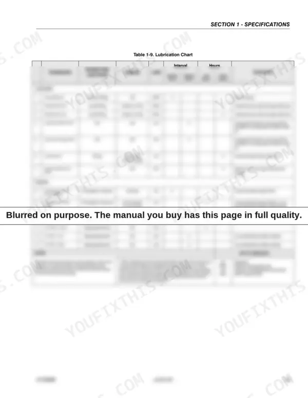
| Specifications | 15-24 | Capacities (Fuel Tank, Hydraulic Oil Tank, Hydraulic System, Torque Hub, Drive, Engine Crankcase) |
| General | 25-38 | Machine Preparation, Inspection, And Maintenance, Service and Guidelines, Lubrication and Information |
| Chassis & Turntable | 39-108 | Torque Hub, Drive (Disassembly, Cleaning and Inspection, Repair, Assembly), Drive Brake - Ausco (Disassembly, Inspection |
| Boom & Platform | 109-128 | Boom Maintenance (Removal, Disassembly Boom Sections, Inspection, Assembly, Installation), Boom Rope Torquing Procedures (Torque Procedures), Wear Pads (Main Boom) |
| Hydraulics | 129-154 | Cylinders - Theory of Operation (Systems Incorporating: Double Acting Cylinders, Holding Valves), Valves - Theory of Operation (Solenoid Control Valve - Rexroth, Relief Valves) |
| Jlg Control System (Ade) | 155-196 | Introduction, To Connect the Jlg Control System Analyzer, Using the Analyzer, Changing the Access Level of the Hand Held Analyzer, Parameters Using the Hand Held Analyzer |
| Schematics | 197-218 | Troubleshooting, Hydraulic Circuit Checks |
Quick Reference Specifications
| Specification | Value | Page |
|---|
| Wire Rope | 15 FT. LBS (20 Nm) | p. 17 |
| Wheel Lugs | 170 FT. LBS. (231 Nm) | p. 17 |
| Hydraulic Filter - In-line (Return - Bypass Type) | 10 Microns Absolute | p. 16 |
| Hydraulic Filter - In-line (Charge) | 10 Microns Absolute | p. 16 |
| Hydraulic Gear Pump (at 1800 RPM) Displacement | 16 cm[3] (1.02 cu. in.) | p. 16 |
| Auxiliary Power Pump Displacement | 14 cm[3] (.244 cu. in.) | p. 16 |
| Foot switch adjustment travel | 1/4 in. (6.35 mm) | p. 127 |
| Horizontal limit switch activation | 4.5° ± 2.5° | p. 121 |
| Horizontal limit switch reset | 5° ± 2.5° | p. 121 |
| Fuel Tank Capacity | 98.4 Liters | p. 15 |
| Hydraulic Oil Tank Capacity | 121 Liters | p. 15 |
| Ford LRG-425 Engine Oil Capacity | 4.25 Liters | p. 15 |