
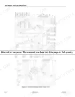
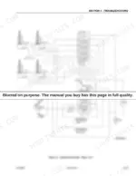
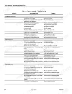
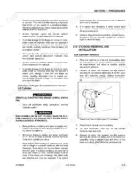
From cylinder repair to drive torque hub rebuilds to pressure settings for both two and four wheel steer machines, the JLG 25RTS, 33RTS, 40RTS service manual PDF walks the hydraulic, drive, brake, and electrical systems on these Sizzor Lifts end to end, 84 pages of factory procedure under OEM number 3120826. Hydraulic schematics trace oil flow from the piston pump through the lift circuit, while wiring diagrams map platform and chassis electrics for tracking down dead controls. Nearly a quarter of the book is troubleshooting, split across platform assembly, chassis, and electrical faults. Set the lift up relief on your 25RTS to 90 bar (1300 psi), then fit a 25 micron nominal element when the hydraulic filter comes due. A lift parked at half height earns nothing. Every hour spent hunting a relief pressure keeps it parked; this bookmarked, text-searchable PDF puts the figure in front of you and gets the platform lifting again.
What's Inside This JLG 25RTS, 33RTS, 40RTS Manual
| System | Pages | Key Topics |
|---|---|---|
| Introduction - Maintenance Safety Precautions | 3-8 | General, Hydraulic System Safety, Maintenance |
| Specifications | 9-16 | Capacities, Component Data, Performance Data, Lubrication, Pressure Settings, Serial Number Locations, Limit Switches, Cylinder Specifications |
| General Servicing and Maintenance Guidelines | 17-20 | Safety and Workmanship, Cleanliness, Component Removal and Installation, Hydraulic System Theory, Relief Valves |
| Cylinder Procedures | 21-27 | Cylinder Checking Procedures, Lift Cylinder Removal and Installation, Cylinder Repair, Disassembly and Assembly |
| Switch and Throttle Adjustments | 28-33 | Tilt Alarm Switch, Limit Switch Adjustment, Drive Pump Start-Up, Throttle Checks and Adjustments (Ford and Deutz), Automatic Choke Adjustment |
| Hydraulic Component Start-Up and Pressure Settings | 34-38 | Hydraulic Component Start-Up, Pressure Setting Procedures (2 W/S and 4 W/S), Oscillating Axle Lockout Cylinder Bleeding |
| Drive System Components | 39-56 | Lockout Cylinder Check, Piston Drive Motor, Drive Torque Hub (2WD/4WD), Drive Torque Hub/Brake (4WD Front) |
| Brake and Fuel Systems | 57-64 | Drive Brake (2WD/2WS), Dual Fuel/Lpg System, Freewheeling Feature, Preventive Maintenance and Inspection Schedule |
| Troubleshooting | 65-84 | Troubleshooting Information, Platform Assembly Troubleshooting, Chassis Troubleshooting, Electrical System Troubleshooting |
Quick Reference Specifications
| Specification | Value | Page |
|---|---|---|
| Piston Hydraulic Pump displacement | 45.9 cm3 (2.8 in.3) | p. 20 |
| Gear Hydraulic Pump displacement | 10.5 cm3 (0.6 in.3) | p. 20 |
| Drive Motor displacement | 6.3 cm3 (2.48 in.3) | p. 9 |
| Hydraulic Filter rating | 25 Microns Nominal | p. 9 |
| Lift Up Relief Pressure | 90 bar (1300 psi) | p. 12 |
| Leveling Jacks Valve Relief Pressure | 90 bar (1300 psi) | p. 12 |
| Sun - 7/8 hex M20 x 1.5 thds holding valve torque | 30 - 35 ft lb (41 - 48 Nm) | p. 26 |
| Sun - 1-1/8 hex 1 - 14 UNS thds holding valve torque | 45 - 50 ft lb (61 - 68 Nm) | p. 26 |
| Hydraulic Oil Tank Capacity | 64.4 liters | p. 9 |
| Fuel Tank Capacity | 56.8 liters | p. 9 |
| Gasoline Engine Crankcase Capacity (w/filter) | 3.2 liters | p. 9 |
| Diesel Engine Crankcase Capacity (w/filter) | 6.5 liters | p. 9 |
JLG 25RTS, 33RTS, 40RTS Common Problems This Manual Covers
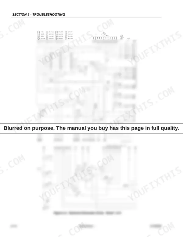
JLG RTS scissor lift completely dead, no response from platform or ground controls
Check the emergency stop at both stations first; it must be pulled out and the enable switch held while operating. Verify hydraulic oil level, the tank holds 64.4 liters. If controls stay dead, test switch continuity against the wiring diagram on page 78 before condemning the controller or control card.
Manual Section: Electrical System Troubleshooting - Control SwitchesMachine will not travel forward or reverse, pump runs but wheels stay still
Check hydraulic oil level before anything else; a low tank (64.4 liter capacity) starves the drive circuit. Inspect supply lines and fittings for restrictions or leaks. Test main relief pressure, which should read 172 bar per page 14, then trace the drive circuit on the hydraulic schematic on page 75.
Manual Section: Chassis Troubleshooting - Drive SystemOnly one function occurs no matter which direction the joystick is moved
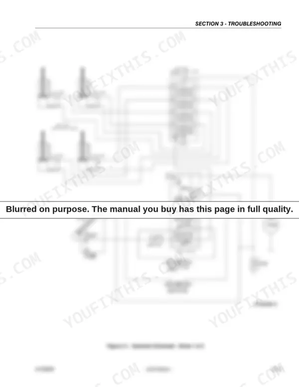
Check solenoid wiring at the valve bank first; loose or swapped leads make one coil fire on every command. Verify each circuit against the wiring diagram on page 78. If wiring checks good, suspect a directional valve stuck in one position; confirm spool movement with system pressure at the 172 bar main relief setting.
Manual Section: Electrical System Troubleshooting - Hand ControllerPlatform drifts down after raising or raises and lowers erratically under load
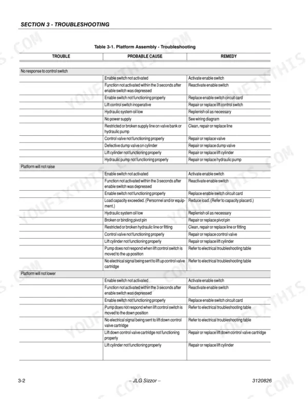
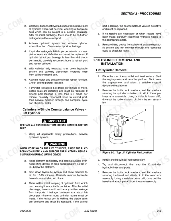
Check the lift cylinder holding valve; a leaking cartridge lets the platform settle under load. Follow the cylinder checking procedure starting on page 21 to isolate cylinder versus valve leakage. When reinstalling a Sun 7/8 hex holding valve, torque it to 30 to 35 ft lb (41 to 48 Nm) per page 26.
Manual Section: Platform Assembly Troubleshooting p. 66Hydraulic pump noisy and cavitating, lift and drive functions weak or intermittent
Check oil level and top off the 64.4 liter tank; cavitation from a low or restricted suction line makes the pump whine and kills lift power. Replace the hydraulic filter, rated 25 microns nominal, if service is overdue. Then verify pressure settings using the start-up procedure beginning on page 34.
Manual Section: Hydraulic System TroubleshootingFrequently Asked Questions
What are the torque specifications for the wheel lugs on the JLG 25RTS, 33RTS, and 40RTS?
All wheel lugs must be torqued to 90 ft lbs. This maintenance task should be performed every 50 hours of operation. p. 9
What is the recommended hydraulic oil for the JLG scissor lift?
JLG Industries recommends Mobilfluid 424 hydraulic oil, which has an SAE viscosity index of 152. For temperatures consistently below -7° C (20° F), the use of Mobil DTE11 is recommended. p. 10
What is the procedure for adjusting the lift up relief pressure on a 25RTS model with a 2-stack Racine valve?
To adjust the lift up relief pressure, you must bottom out the lift up function and adjust the relief to 90 bar (1300 psi). p. 35
What is the required thickness for the sliding wear pads?
The original thickness of the sliding wear pads is 50.8 mm (2.0 in.). They should be replaced when they are worn down to 47.5 mm (1.87 in.). p. 20
What is the torque spec for the lift cylinder piston nut on a JLG 25RTS, 33RTS, 40RTS Sizzor Lift?
The lift cylinder piston nut should be torqued to 400 ft lb (542 Nm). p. 26
How will I receive this JLG 25RTS Service Manual?
This is a 84-page searchable PDF ready for immediate download. Works on any device, so pull it up on your phone while you're under the hood. No shipping, no waiting.
Can I print a copy of this JLG 25RTS Service Manual for the shop?
Yes. Many buyers print one chapter at a time for their own shop and keep the rest on a tablet.


Reviews
There are no reviews yet.