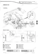

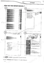
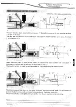
The hydraulics chapter is the hardest part of these machines. It holds the diagram keys, the Privilege hydraulic diagrams per model (the MT 1840 R is on page 228), manometer box pressure checks and component removal and refit.
The rest of the book covers the engine, transmission, axles and brakes, the triplex boom and the electrics. Refitting the engine box? The converter to flywheel screws take 30 Nm +/-10% (page 50). There are electric diagrams for Privilege, EP+A and inching machines, plus LCD cluster error codes with possible causes.
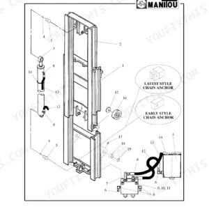
The diagrams give every component a code, such as Y10, Y11, B3 and X8. That lets you name the exact solenoid, switch or connector at the parts counter and get the right one the first time.
What's Inside This Manitou MT 1436–1840 Privilege Series Repair Manual
| System | Pages | Key Topics |
|---|---|---|
| Engine | 1-65 | Engine Characteristics and Specifications, Synoptics, Cooling Circuit, Components Location, Control and Adjustment, Engine Box Assembly Removal and Refit |
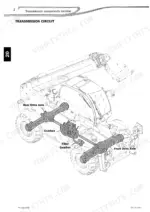
| Transmission | 66-84 | Transmission Characteristics, Gear Diagrams (Standard and Inching), Components Location, Control and Adjustment, Universal Joints, Converter |
| Axles and Brakes | 85-109 | Axle Characteristics, Control and Adjustment, Axle Troubleshooting, Specific Axle Tooling, Service and Parking Brake |
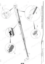
| Boom | 110-166 | Boom Characteristics and Specifications (Triplex), Boom Positioning, Anti-Fall Strut |
| Hydraulics | 167-413 | Hydraulic Diagram Keys, Privilege Hydraulic Diagrams per Model, Hydraulic Components Location, Pressure Checks with Manometer Box, Components Removal and Refit |
| Electrics | 414-677 | Electric Characteristics and Specifications |
| Electrical Diagrams | 678-916 | Electric Diagrams per Model (Privilege, EP+A, Inching) |
| Electric Components Location | 917-1003 | Connectors, Harnesses |
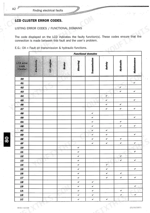
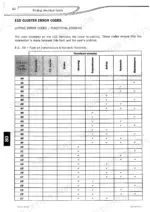
| Electric Troubleshooting | 1004-1019 | LCD Cluster Error Codes, Functional Domains and Possible Causes of Errors |
Quick Reference Specifications
| Specification | Value | Page |
|---|---|---|
| MT 1436 R, MT 1440, MT 1440 A, MT 1440 EP, MT 1840, MT 1840 R, MT 1840 A | ||
| Maximum engine speed (empty) | 2350 rpm | p. 24 |
| Maximum engine speed (loaded) | 2200 rpm | p. 24 |
| Engine/gearbox coupling screw torque | 95 Nm ±10% | p. 49 |
| Engine silent block bracket screw torque | 23 daNm ±10% | p. 49 |
| Converter to flywheel screw torque | 30 Nm ±10% | p. 50 |
| Converter pressure limiter | 8.5 bar | p. 68 |
| Service brake friction material | Paper N266 | p. 88 |
| MT 1440 | ||
| Engine | Turbo I.C. engine 1104C-44 T, 74.5 kW | p. 213 |
| MT 1440 EP | ||
| Accumulator | 35 bar | p. 257 |
Manitou MT 1436–1840 Privilege Series Common Problems This Manual Covers
Gear acquisition fault or a gearbox oil pressure warning on the LCD cluster
Start with the LCD cluster error codes in the Electrics section. Page 1013 lists a gear acquisition fault, a faulty forward/reverse pressure sensor, and gearbox oil pressure or temperature warnings as the possible causes. Then go to transmission control and adjustment and check the converter pressure limiter against 8.5 bar (page 68). If the oil needs changing, page 36 covers draining the gearbox by pulling out the plug.
Manual Section: Electrics - LCD cluster error codes / Transmission - control and adjustment p. 1013Boom suspension not working
Boom suspension is switched by solenoid valves Y10 and Y11, shown on the electric diagram on page 861. Check power and earth at those two solenoids using the electric diagrams and harness pages for your model. If the electrics test good, use the hydraulic components location pages and the Privilege diagram for your machine. Then pressure check the circuit with the manometer box (page 323).
Manual Section: Electrics - electric diagrams and components location / Hydraulics - pressure checks p. 861Engine oil pressure warning on the cluster
Page 1013 lists the engine oil pressure warning under engine faults, next to engine computer, water temperature and air filter clogging. The engine oil pressure switch is B3, at position K7 on the electric diagram (page 843). Test the switch and its wire before you condemn the engine. Then use engine control and adjustment to confirm the actual oil pressure.
Manual Section: Electrics - LCD cluster error codes / Engine - control and adjustment p. 1013Service brake discs need replacing and the friction material has to match
The Axles and Brakes section covers the service and parking brake and the axle-specific tooling. It gives the service brake friction material as Paper N266 (page 88), so you can order the correct discs the first time. Before you open the axle, follow page 7. Put the machine on flat ground, block the wheels, remove the key, let it cool and release all circuit pressure.
Manual Section: Axles and Brakes - service and parking brake p. 88Frequently Asked Questions
What torque for converter, coupling and engine mount screws on a Manitou MT 1436–1840 Privilege Series engine box refit?
Converter to flywheel screws take 30 Nm +/-10% (page 50). Engine/gearbox coupling screws take 95 Nm +/-10%, and the engine silent block bracket screws take 23 daNm +/-10% (both page 49). Note that the bracket figure is in daNm, not Nm. Read it wrong and those screws end up badly under-tightened. p. 50
The LCD cluster is showing a transmission fault. What does the manual point me to?
Page 1013 lists the possible causes for transmission faults. They are a gear acquisition fault, a faulty forward/reverse transmission pressure sensor, and gearbox oil pressure or temperature warnings. Check the sensor and its wiring first. Then check pressures against the transmission control and adjustment section, which gives the converter pressure limiter as 8.5 bar (page 68). p. 1013
What equipment do I need to check hydraulic pressures properly?
The manual measures pressures with either the basic or the digital Manitou manometer box. Each box holds the fittings and gauges for Manitou products (page 323). The pressure check procedures are written around that kit. Use it on figures like the 35 bar accumulator value on page 294 and you will be measuring the same way the book does. p. 323
Where are the engine oil pressure switch and the engine stop electrovalve on the wiring?
Engine oil pressure switch B3 sits at grid position K7 on the electric diagram (page 843). The engine stop electrovalve is connector X8 in the connector list (page 918). With those two references you can find the right plug on the harness instead of tracing wires along the engine box. p. 843
What maximum engine speed should I see when checking the engine?
Maximum engine speed is 2350 rpm empty and 2200 rpm loaded (page 24). Take both readings so you can compare the machine under load against the specification. The MT 1440 hydraulic key lists the Turbo I.C. 1104C-44 T engine at 74.5 kW (page 213). Having that rating on paper helps when you deal with engine parts suppliers. p. 24