
Getting a Manitowoc 999 crawler crane off the trailer and into its first lift with nothing missed is what the 288 pages of this Manitowoc 999 operator manual PDF (OEM ID 042-14_v2) are for. Assembly and rigging fill nearly half the book: raising the mast, installing crawlers and counterweight, fitting #22E, #22EL or #82 boom butts, the #134 jib, and load line and boom hoist reeving down to wedge socket anchoring. Before that, the operating chapter walks you through cab controls, hand signals, fault displays, drum and swing diagnostics, calibration and wind limits. Never exceed 70,000 lb on any carbody jack; the tank heater should hold hydraulic oil 30°F above ambient. On a remote pad, nobody is there to ask. Bookmarks and a searchable text layer lead straight to the lube guide and fuse ratings, so you order the right oil, fuse or decal the first time and get the crane assembled, inspected and lifting.
What's Inside This Manitowoc 999 Operator Manual
| System | Pages | Key Topics |
|---|---|---|
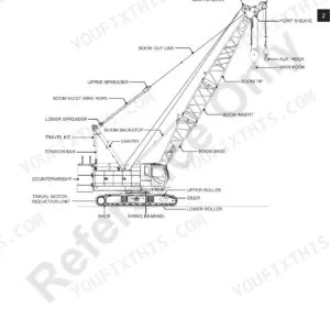
| Introduction | 1-40 | Crane Data, Crane/Attachment Identification, Ownership Registration, Manitowoc Dealer, Crane Orientation |
| Safety Information | 41-72 | Continuous Innovation, Nameplates and Decals, Safety Messages (General, Safety Alert Symbol, Signal Words, Symbol Identification) |
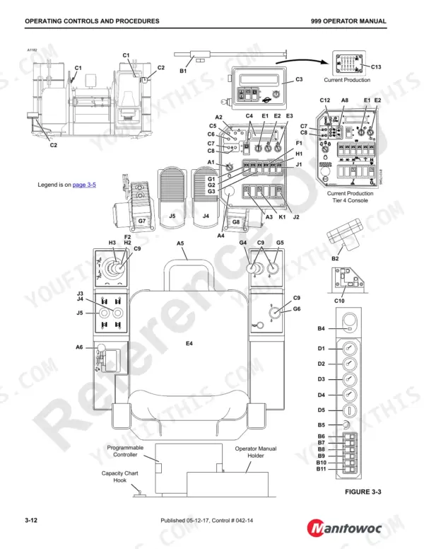
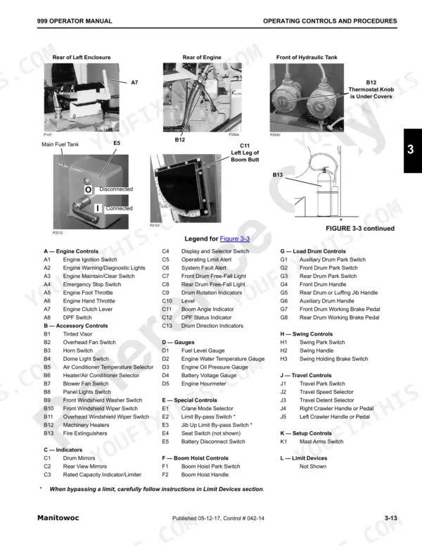
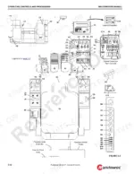
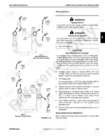
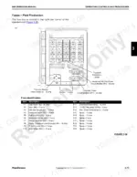
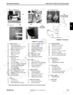
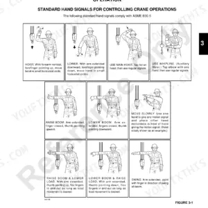
| Operating Controls and Procedures | 73-146 | Standard Hand Signals for Controlling Crane Operations, Symbol Identification |
| General Setup and Installation Information | 147-160 | Rigging Drawings, Crane Weights, Hose and Cable Cleanliness, Cold Weather Mast Operation, Shipping Crane Components |
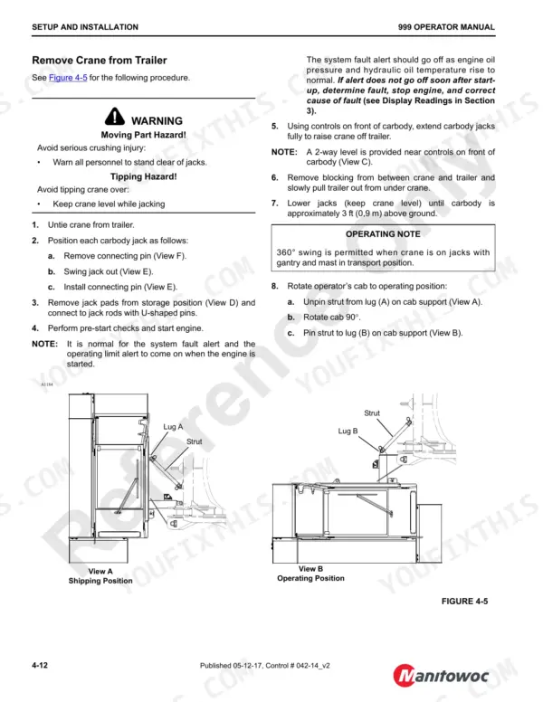
| Crane Assembly and Disassembly | 161-171 | Pre-Start Checks, Raising Mast, Installing Crawlers, Removing Crawlers, Installing Assembly Block |
| Counterweight Installation and Removal | 172-175 | Assemble Counterweight, Install Counterweight, Remove Counterweight, Counterweight Removal Sequence |
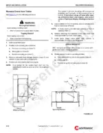
| Boom Butt Installation and Removal | 176-197 | Remove Boom Butt From Trailer, Install #22E or #22EL Boom Butt, Connect #82 Boom Butt to Boom, Disconnect Boom Butt From Boom |
| Boom and Jib Rigging | 198-251 | Identifying Boom and Jib Components, Jib Installation, Jib Removal, Rigging Winch Operation |
| Wire Rope Installation and Reeving | 252-276 | Rigging Winch Operation, Wire Rope Installation, Seizing and Cutting Wire Rope, Load Line Reeving, Universal Anchor Joint, Boom Hoist Reeving |
| Lubrication | 277-280 | Lube and Coolant Product Guide, Greasing Sheave Bearings, Engine Oil, Gear Oil, Hydraulic Oil |
| Maintenance Checklist | 281-288 | Fiberglass Maintenance |
Quick Reference Specifications
| Specification | Value | Page |
|---|---|---|
| Swing torque adjustment range | 25% to 100% | p. 112 |
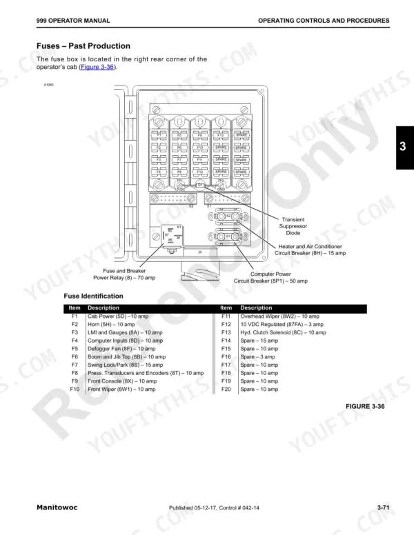
| Fuse and Breaker Power Relay (8) | 70 amp | p. 145 |
| Computer Power Circuit Breaker (8P1) | 50 amp | p. 145 |
| Maximum load on each carbody jack | 70,000 lb | p. 152 |
| Hydraulic tank heater temperature (warmer than ambient) | 30°F | p. 139 |
| Engine coolant heater power (Past Production, S/N 9991037) | 1,250 watt | p. 139 |
| Engine coolant heater power (Past Production, S/N 9991176) | 1,500 watt | p. 139 |
| Engine coolant heater power (Current Production Tier 3) | 1500 watt | p. 141 |
| Engine coolant heater power (Tier 4 Production) | 1000 watt | p. 143 |
| Spanner nut torque for sheave cluster | 75 ft-lbs | p. 242 |
| Maximum load for No. 1.5 pad eye | 1,000 lb | p. 261 |
| Maximum load for mast assembly | 50,000 lb | p. 172 |
Manitowoc 999 Common Problems This Manual Covers
Manitowoc 999 Cummins QSM11, QSL9 or Caterpillar 3176C engine showing active fault code on diagnostic lights
Check the diagnostic lights to identify every active fault code using the engine diagnostics procedure for your engine (Cummins QSM11, QSL9 Tier 4 or Caterpillar 3176C). Land the load before troubleshooting. Record each code, correct the cause, and confirm the lights clear before the crane goes back to work.
Manual Section: Engine Diagnostics (Cummins QSM11, QSL9 Tier 4, Caterpillar 3176C)QSL9 Tier 4 DPF high temperature, DPF condition or regeneration inhibit indicator active
Check the DPF diagnostics for the Cummins QSL9 Tier 4 and note which indication is active: high temperature, DPF condition or regeneration inhibit. Verify the regeneration inhibit setting is what you intended for the job site. Correct the active condition following the DPF diagnostics procedure and confirm the indicator clears before the crane goes back to lifting.
Manual Section: DPF Diagnostics (Cummins QSL9 Tier 4)System fault active for hydraulic tank fluid level, hydraulic tank fluid temperature or hydraulic filter
Check which hydraulic fault is active against the System Faults table (Table 3-6). Verify hydraulic oil level and oil type against the Lube and Coolant Product Guide on page 277. In cold weather, confirm the hydraulic tank heater keeps oil 30°F warmer than ambient, as listed on page 139. Inspect the filters flagged by the fault.
Manual Section: System Faults (Table 3-6)Crane function stops at block up, max up, max down or load moment operating limit
Check which limit is active against the Operating Limits table (Table 3-5): block up, max down, max up, bail limits, gantry down, load moment or mast system. Verify the load and rigging match your lift plan before moving. Never bypass a limit to finish the pick; correct the condition, then confirm the limit clears.
Manual Section: Operating Limits (Table 3-5)Drum, swing or track function not responding to controls while the engine runs normally
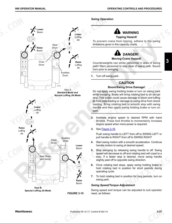
Check the Crane Diagnostics for the drums, swing, track and accessory system, and monitor controller inputs and outputs while a second person works the control. Verify the input changes when the handle moves. For weak swing, confirm the swing torque setting on page 112, adjustable from 25% to 100%, is not set too low.
Manual Section: Crane Diagnostics (Drums, Swing, Track, RIN, Accessory System)Swing lock/park, LMI and gauges, or pressure transducer and encoder circuits have no power
Check fuse identification for your production run: page 145 covers past production and page 146 covers current production. On past production cranes, test F7 Swing Lock/Park (15 amp), F3 LMI and Gauges (10 amp) and F8 Pressure Transducers and Encoders (10 amp). Replace with the same rating and verify the LMI powers up before lifting.
Manual Section: Electrical System (Fuses - Past Production) p. 145Frequently Asked Questions
How do I calibrate the Manitowoc 999 hydraulic system?
To calibrate the hydraulic system, refer to the Hydraulic System Calibration Procedures in Section 2 of the Service Manual. This procedure ensures proper operation of the crane functions. p. 118
What is the procedure for removing the auxiliary load drum from the crane?
To remove the auxiliary load drum, first remove the hydraulic motor and drum encoder from the drum assembly. Then, hook an assist crane to the lifting lugs on the auxiliary load drum and pin it to the boom butt lugs, ensuring the motor side is on the left side of the butt. p. 214
What is the torque spec for the flange screws on the Manitowoc 999 crawler drive shaft?
When installing the crawler drive shaft, the flange screws must be torqued to 74 ft-lb (100 Nm). p. 171
What is the maximum load capacity of the No. 1.5 pad eye used for wire rope reeving on the Manitowoc 999 crane?
For the No. 1.5 pad eye, the maximum single line pull is 1,000 lb (4,45 kN). p. 261
What torque do the nuts on the removable diagonal lacings of the Manitowoc 999 #22E inserts need?
When reinstalling the removable diagonal lacings on #22E inserts, the nuts must be torqued dry to 300 ft-lb (407 N•m). p. 230
Is this Manitowoc 999 manual a PDF I download?
One searchable PDF covering 288 pages, delivered instantly. No disc, no shipping, no waiting on the post.
Can I print specific sections of this Manitowoc 999 Operator Manual?
Yes. Print a single page or a chapter for your own shop use, on letter or A4.


Reviews
There are no reviews yet.