A hose lets go mid-harvest, the rotor quits and the combine sits dead in the stubble with the hydrostatic pumps back in neutral. This is the Massey Ferguson 9695 and 9795 Workshop Service Manual, publication 4283358M1, with all 12 chapters in one PDF.
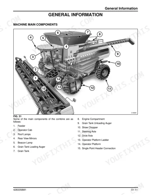
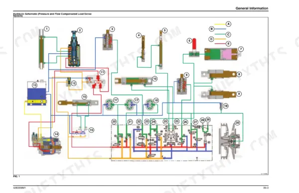
It covers the feeder house and feed reverser, the rotor and concaves, the cleaning shoe, the grain tank and unloading auger, both axles, hydraulics, electrical, electronics and the cab. The engine chapter covers only the drives, cooling and fuel systems, not an internal rebuild. It includes hydraulic schematics, wiring diagrams for each subsystem and the Console II calibration pages.
A lot of repairs stall with a final drive hanging off the axle and nobody sure of the bolt torque. The numbers are in here, so you can get the combine cutting again while the weather holds.
What's Inside This Manual
| System | Pages | Key Topics |
|---|---|---|
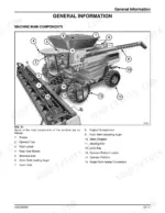
| General Information | 1-136 | Safety, Lubrication and Maintenance Intervals, Tires and Wheels, Tire Pressure |
| Specifications | 137-284 | 9695 and 9795 Specification Sheets, Fluid Capacities, Hydraulic Component Data, Wheel Bolt Torque, Standard and Special Torque Charts, Dimensions |
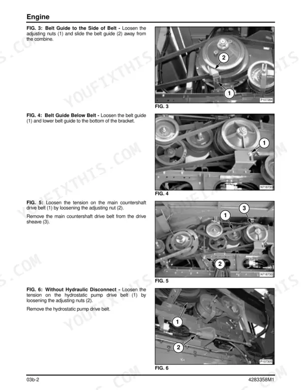
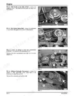
| Engine - Drives, Cooling and Fuel | 285-376 | Engine-Side Drives, Cooling Package, Fuel System (No Internal Engine Overhaul) |
| Material Handling | 377-758 | Feeder House, Feeder Conveyor, Feed Reverser |
| Material Discharge | 759-882 | Grain Tank, Unloading Auger and Swing, Chaff Spreader |
| Rear Axle | 883-1132 | Steering Axle, Power Rear Wheel Drive, Wheel Motors |
| Threshing and Separating | 1133-1406 | Rotor, Rotor Gearbox, Concaves, Cleaning Shoe, Sieve and Chaffer |
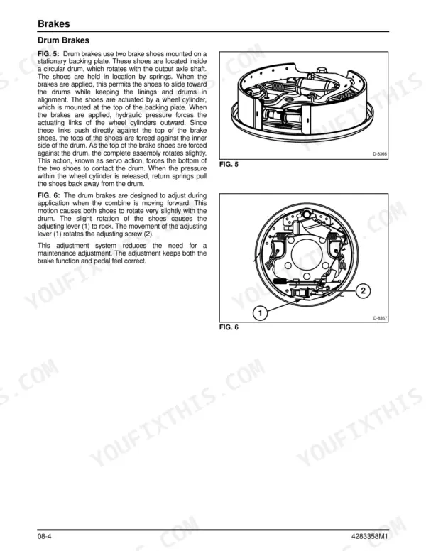
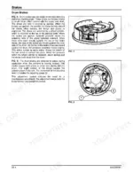
| Front Axle | 1407-1572 | Final Drives, Transmission, Brakes |
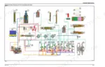
| Hydraulics | 1573-2162 | Hydraulic Control Valve, Hydrostatic Rotor and Propel Drive, Steering Cylinders, Troubleshooting Tables, Hydraulic Schematics |
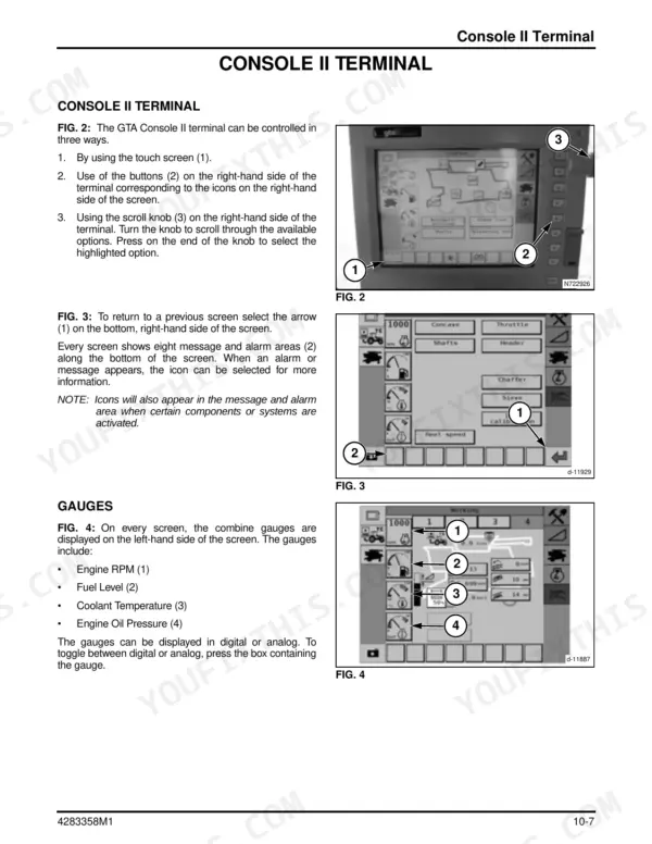
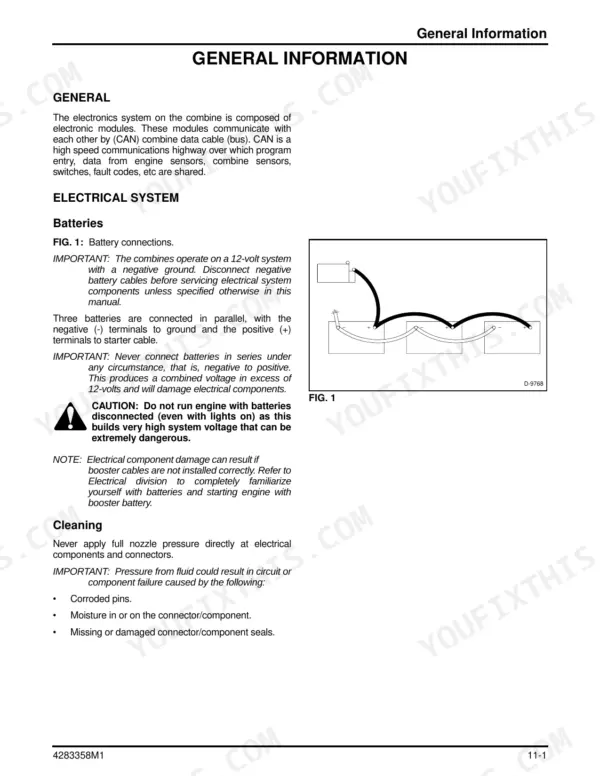
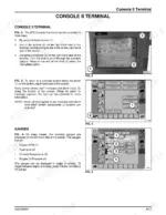
| Electrical | 2163-2364 | Console II Terminal and Calibrations, Grounds, Wiring Diagrams per Subsystem, Power Distribution, Thresher Clutch, Batteries |
| Electronics | 2365-2410 | Electronic Control Modules and Switch Circuits |
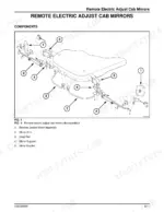
| Cab and HVAC | 2411-2628 | Cab, Air Conditioning and Heating |
Quick Reference Specifications
| Specification | Value | Page |
|---|---|---|
| Engine make and model | Sisu 84CTA Tier III 8.4L, 6 in-line, turbocharged and charge air cooled | p. 150 |
| Hydraulic system complete, standard rear axle | 90.8 liters (95.9 qt.) | p. 150 |
| Hydraulic system complete, power rear wheel drive axle | 97.6 liters (103.1 qt.) | p. 150 |
| Hydraulic reservoir | 31.4 liters (33.2 qt.) | p. 150 |
| Rotor gearbox oil | 4.0 liters (8.0 pt.), SAE 85W-90 API-GL-5 | p. 150 |
| Final drives (each) | 5.68 liters (6 qt.), SAE EP 80-90 | p. 150 |
| Front wheel to final drive flange torque | 813 Nm (600 lbf ft.) | p. 148 |
| Inner dual to outer dual torque | 542 Nm (400 lbf ft.) | p. 148 |
| Standard rear axle wheel to hub torque | 200 Nm (150 lbf ft.) | p. 148 |
| Power rear axle wheel to drive motor flange torque | 406 Nm (300 lbf ft.) | p. 148 |
| Final drive to drive axle torque | 1627 Nm (1200 lbf ft.) | p. 275 |
| Rotor length / diameter | 3.56 m (140 in) / 700 mm (27.56 in) | p. 142 |
| Grain tank capacity | 10 570 liters (300 bu) | p. 144 |