
Part of the New Holland Repair Manuals.
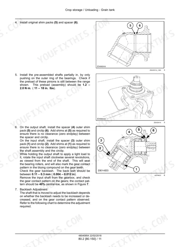
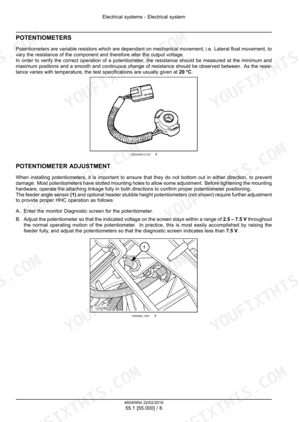
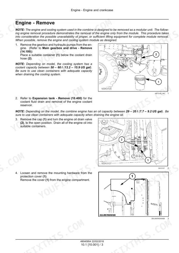
This is New Holland service manual 48040954 for the CR5.85 rotary combine. It is the English edition from February 2018, built in Brazil for Latin America.
It covers the Machine Standard and the Self Leveling version, engine code F4HFP613B*H006. Inside are the main gearbox and clutch packs, the hydrostatic pump and motor, and the powered rear axle. It also covers hydraulics and header controls, threshing, cleaning, unloading, the electrical schematic sheets and fault codes.
What's Inside This New Holland CR5.85 Manual
| System | Pages | Key Topics |
|---|---|---|
| Introduction | 1-24 | Model Applicability, Product and Engine Links, Contents, Safety Rules, Basic Instructions, Torque Guidance, Roller Chain Wear |
| Engine | 25-96 | Engine Removal and Installation, Fuel Injection, Air Cleaners, Intake and Exhaust, Cooling System, Rotary Screen, Air Compressor |
| Main Gearbox and Drive | 97-156 | Main Gearbox, Main Clutch Packs, Unload Clutch, Hydraulic Pump Drive, Gearbox Disassembly, Shimming and Rolling Torque |
| Transmission | 157-244 | Mechanical Transmission, External Shift Controls, Gearbox Internal Components, Shifting Discs, Driven Shafts, Differential |
| Front Axle System | 245-266 | Final Drives, Sectional and Exploded Views, Bearing Preload, Assembly and Installation, Wheel Stud Replacement |
| Hydrostatic Drive Controls and Reservoir | 267-293 | Multifunction Valves, Pressure Limiter, High Pressure Relief, Shuttle Spool and Flushing Valve, Pressure Testing, Thermostatic Bypass Valve |
| Hydrostatic Pump, Motor and Transmission | 294-361 | S90 Variable Displacement Pump, Fixed Displacement Motor, Charge Pressure Setting, Servo Valve, Hydrostatic Schema, Filling and Start-Up, Troubleshooting |
| Rear Hydrostatic Transmission | 362-438 | Powered Rear Axle, Selector Valve, Optional Flow Regulator, MG18 Wheel Motor, Motor Overhaul, Two-Speed Valve Testing |
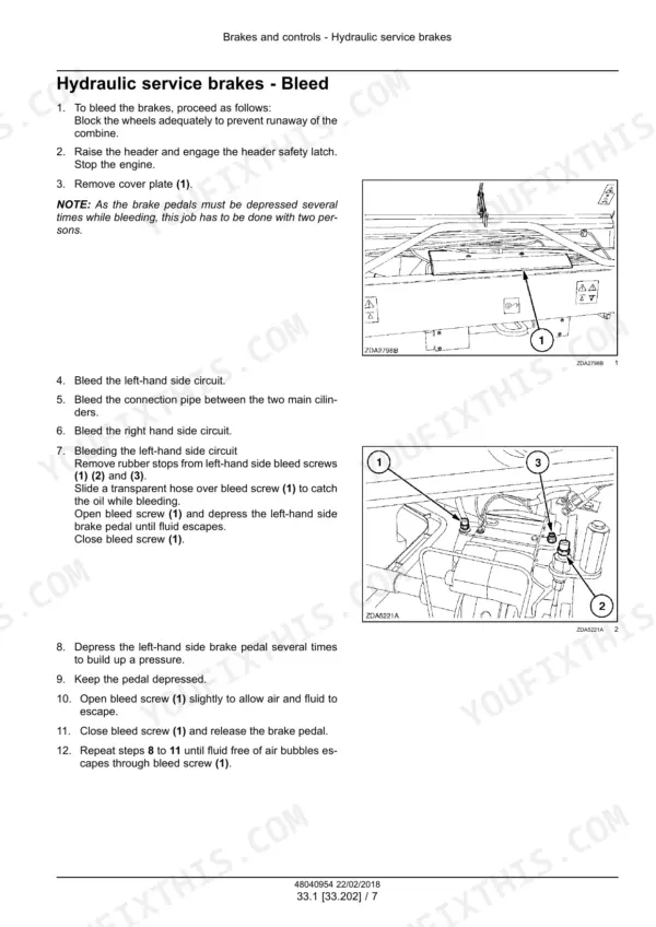
| Brakes and Controls | 439-476 | Hydraulic Service Brakes, Master Cylinder, Brake Bleeding, Brake Discs and Linings, Parking Brake |
| Hydraulic Systems | 477-606 | Hydraulic Schemas, Reservoir and Filters, Variable Displacement Pump, Pump Control Valves, Main Control Valve, Low Pressure System, Header Lift and Leveling, Header Reverser and Variator |
| Steering | 607-628 | Steering Control, Steering Motor, Hydraulic Control Components, Autoguidance Steering |
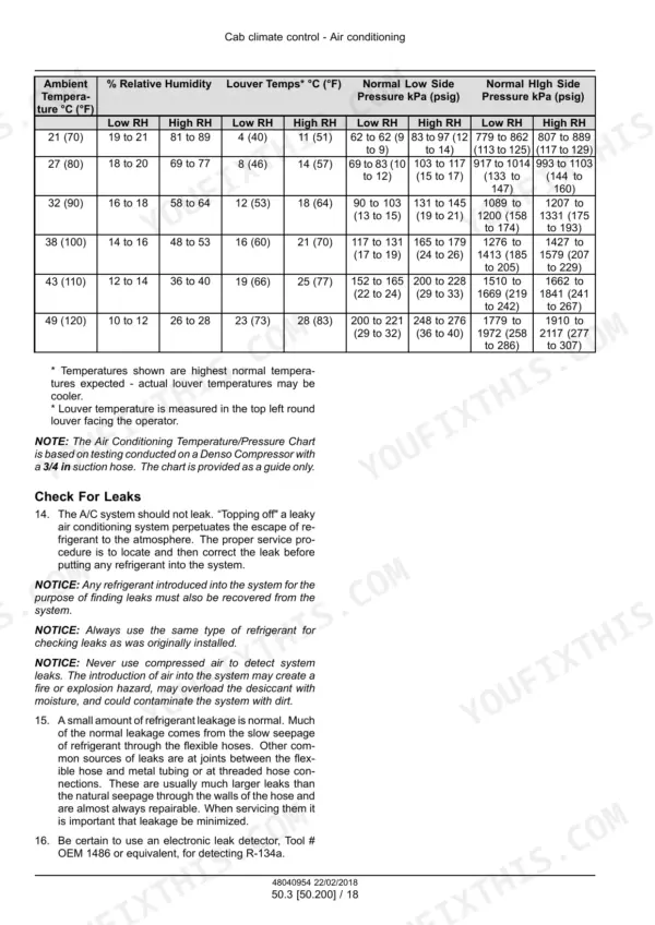
| Cab Climate Control | 629-718 | Heating, Ventilation, Air Conditioning, Compressor and Condenser, Refrigerant Servicing, Pressure Tests, Troubleshooting |
| Electrical Systems | 719-765 | Fuses and Switches, Electrical Standards, H-Bridge Operation, Resistance and Continuity Tests, Short Circuit Tests, Intermittent Fault Diagnosis |
| Harnesses, Connectors and Wiring Diagrams | 766-937 | Connector Tools, Electrical Schematic Sheets, Starting and Engine Circuits, Header and Feeder Circuits, Threshing and Cleaning Circuits, CAN Network, Lighting and a/C Circuits, Hydrostatic Pump Control |
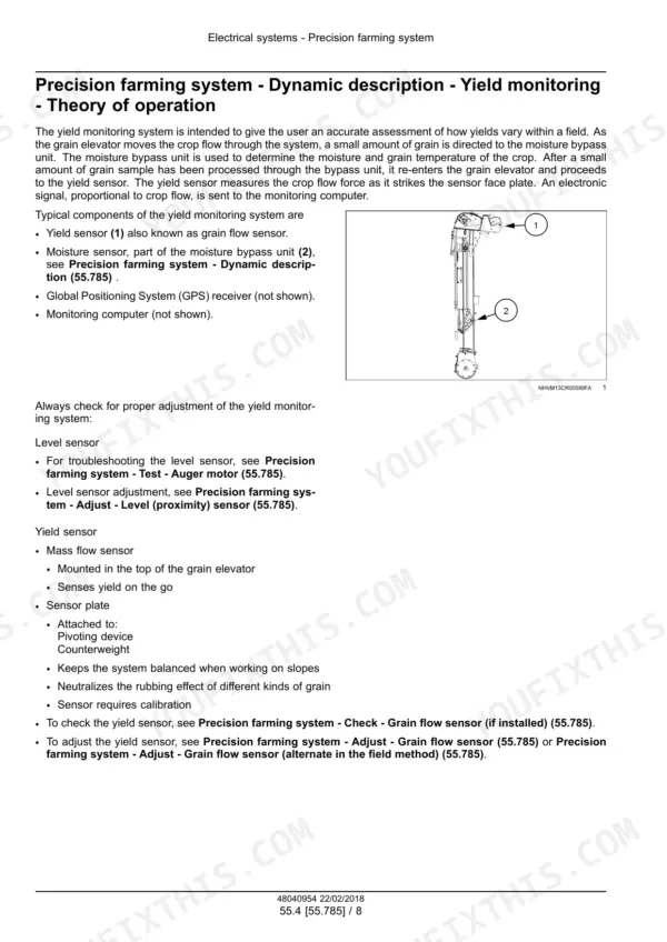
| Brake, Precision Farming and Rotor Sensors | 938-977 | Service Brake Pressure Switch, Moisture Bypass Unit, Grain Flow Sensor, Yield Sensor Adjustment, Parking Brake Control, Rotor Reference Speed Sensor |
| Fault Codes (DTC) | 978-1056 | CM1 Faults, CM2 Faults, HHC Faults, RHM Faults, Current and Resistance Checks, Wiring and Controller Diagnosis |
| Product Feeding | 1057-1160 | Feed Chain and Floating Roll, Feeder Housing, Feeder Shafts, Feeder Drive, Feeder Reverse, Rotor |
| Threshing | 1161-1318 | Threshing Engagement, Drive System, Rotors, Rotor Gearboxes, Rotor Housing, Electric Variator Control, Concaves, Concave Controls |
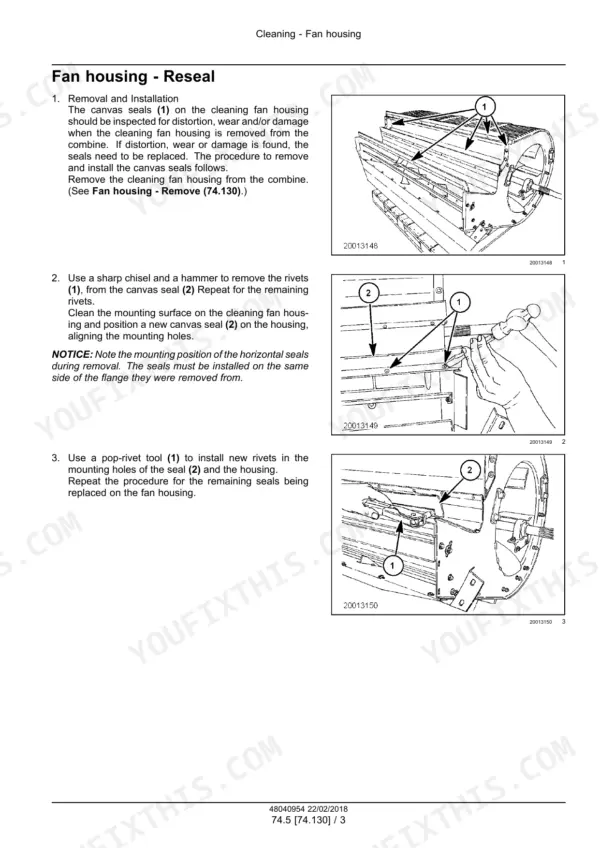
| Cleaning | 1319-1410 | Self-Leveling Cleaning Shoe, Cleaning Drive, Grain Pan, Cross Auger Housing, Fan Housing, Fan Drive and Troubleshooting, Tailings Return |
| Crop Storage and Unloading | 1411-1510 | Clean Grain Elevator, Elevator Chain and Shafts, Grain Tank, Delivery Gearbox, Unload Drive, Unloading Augers |
| Platform, Cab, Bodywork and Decals | 1511-1555 | Operator Platform, Access Ladder, Protections and Footboards, Pneumatic Operator Seat, Seat Testing and Diagnosis |
| Special Tool Index | 1556-1559 | Engine Tools, Hydrostatic Test Tools, Electrical Connector Tools, Threshing Tools, Kit References |
Quick Reference Specifications
| Specification | Value | Page |
|---|---|---|
| Engine code | F4HFP613B*H006 | p. 3 |
| Engine oil capacity (depending on model) | 29 - 35 l (7.7 - 9.2 US gal) | p. 28 |
| Cooling system coolant capacity (depending on model) | 50 - 60 l (13.2 - 15.9 US gal) | p. 28 |
| R-134a refrigerant capacity | 3.6 kg (7.94 lb) | p. 672 |
| Maximum air tank pressure | 10 bar ( 145 psi) | p. 80 |
| Hydraulic pump drive housing torque | 190-210 N·m ( 140-155 ft. lbs.) | p. 100 |
| Wheel nuts torque | 610-732 Nm ( 450 - 540 ft.lbs ) | p. 248 |
| Hydrostatic pressure limiter | 420 bar ( 6090 psi) | p. 334 |
| Hydrostatic relief valve | 450 bar ( 6525 psi) | p. 334 |
| Hydrostatic pump rated speed | 3100 rpm | p. 297 |
| Hydrostatic pump maximum speed | 3400 rpm | p. 297 |
| Charge pump pressure | 38 bar (551 psi) | p. 297 |
| Hydrostatic motor rated speed (11/111 final drives) | 3300 rpm | p. 298 |
| Hydrostatic motor maximum speed (11/111 final drives) | 3650 rpm | p. 298 |
| Hydrostatic motor flow at rated speed | 365 l/min ( 96.4 gal/min) | p. 298 |
| Powered rear axle selector valve flow | 238 L/min (63 US gpm) | p. 365 |
| MG18 rear wheel motor maximum operating pressure | 6500 psi (450 bar) | p. 367 |
| Low pressure pump regulated system pressure | 25 bar ( 363 psi) | p. 550 |
| Cleaning fan drive sheave bolt torque | 75 N·m ( 55.4 ft. lbs.) | p. 1378 |
| Cleaning fan driven sheave nut (inner) torque | 170 N·m ( 125.5 ft. lbs.) | p. 1378 |
New Holland CR5.85 Common Problems This Manual Covers
Machine will not operate in either direction
Start with the hydrostatic filter. A blocked filter is the listed cause when the combine will not move forward or reverse. Replace the filter as described in the hydrostatic transmission troubleshooting in the Hydrostatic Pump, Motor and Transmission section. Then check charge pressure against the 38 bar (551 psi) charge pump pressure.
Manual Section: Hydrostatic transmission - Troubleshooting p. 357Combine does not move when the hydrostatic control lever is moved
Before you pull anything apart, check the transmission gear selector. If it is in neutral, the combine will not move when the lever is moved. Select the required gear. If the linkage will not pull it into gear, the Transmission section covers the external shift controls.
Manual Section: Hydrostatic transmission - Troubleshooting p. 357Hydrostatic oil temperature too high
A blocked oil cooler is the listed cause. Clean it or replace it as required, following the hydrostatic transmission troubleshooting in the Hydrostatic Pump, Motor and Transmission section. Check the rotary screen in the Engine section too, and replace the cooler if the core is damaged.
Manual Section: Hydrostatic transmission - Troubleshooting p. 358Cleaning fan vibrates during operation
A flat or worn spot on the belt will set the cleaning fan shaking. Replace the belt using the fan drive procedure in the Cleaning section. With the sheaves exposed, torque the drive sheave bolt to 75 N·m ( 55.4 ft. lbs.) and the inner driven sheave nut to 170 N·m ( 125.5 ft. lbs.).
Manual Section: Fan drive system - Troubleshooting p. 1398Frequently Asked Questions
Which New Holland combine does this service manual cover?
It covers the New Holland CR5.85 rotary combine built in Brazil, under manual number 48040954, in English, dated February 2018. Two versions are listed: Machine Standard and Machine Standard with Self Leveling. Both use engine code F4HFP613B*H006 and are listed for Latin America. p. 2
What engine oil and coolant capacities does the New Holland CR5.85 service manual list?
The engine section gives oil capacity as 29 - 35 l (7.7 - 9.2 US gal) and coolant capacity as 50 - 60 l (13.2 - 15.9 US gal). Both ranges depend on the model. p. 28
What are the hydrostatic transmission pressure limiter and relief settings on the New Holland CR5.85?
The pressure limiter is set at 420 bar ( 6090 psi) and the relief valve at 450 bar ( 6525 psi). p. 334
Are the cleaning fan drive torques listed?
Yes. The drive sheave bolt is 75 N·m ( 55.4 ft. lbs.) and the inner driven sheave nut is 170 N·m ( 125.5 ft. lbs.). p. 1378
Does the manual include wiring diagrams, hydraulic schematics and fault codes?
Yes, it has all three. The harnesses and connectors section has numbered electrical schematic sheets from SH03 STARTING to SH84 ENGINE BLOW OFF / DUST OFF, including SH07 ENGINE and SH68 HYDROSTATIC PUMP CONTROL. Hydraulic schematics include the hydrostatic schema and high pressure circuit diagrams for Auto Guidance Ready and non-AGR machines. The fault codes DTC section has diagnostic cards such as E0042-06 - Current Sense Reverser Short Circuit and E0052-11 - Feeder Clutch Valve Unidentified Failure Code. p. 777







Reviews
There are no reviews yet.