
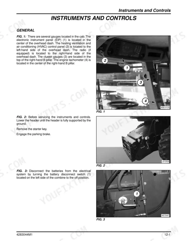
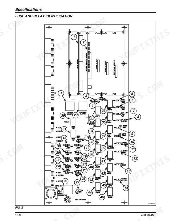
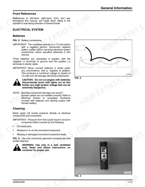
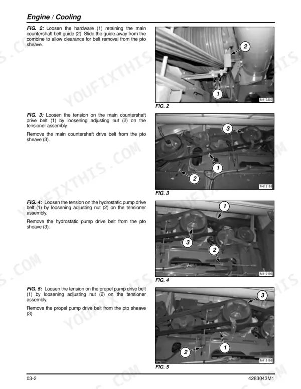
You're about to crawl under the feeder house with a drop light, or set a gauge on a hydraulic test port. Keep this book open on the platform while you work. It covers the Massey Ferguson 9895 rotary combine in 12 chapters over 2374 pages.
Few things hurt more than a combine stuck in the shed while the neighbors are cutting. The hydraulics chapter covers priming, start-up, pump tests and the schematics. The electronics chapter explains the instrument panel engine codes and the console controller fault codes.
Chapters 01-09 carry part number 4283043M1 and chapters 10-12 carry 4283044M1. The other chapters cover the rotor, concaves, cleaning shoe, rear axle, final drives, wiring and cab. Find the fault, fix it and get the header back in the crop.
What's Inside This Massey Ferguson 9895 Manual
| System | Pages | Key Topics |
|---|---|---|
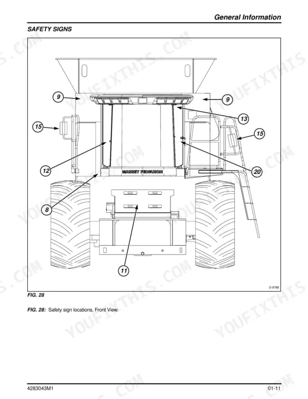
| General Information | 1-140 | Safety, Combine Identification, Diesel Fuels, Lubrication and Maintenance, Drive Belts, Roller Chains, Storage, Torque Charts |
| Specifications | 141-230 | Engine, Electrical, Cab and Air Conditioning, Hydraulic Pressures, Capacities, Weights, Standard and Special Torque Tables |
| Engine | 231-296 | Engine Oil, Fuel System, Cooling System, Air Cleaner, Engine Drive Belt |
| Material Handling | 297-674 | Feeder House, Feeder Conveyor, Feed Reverser, Header Drives |
| Material Discharge | 675-792 | Grain Tank, Unloading Auger, Straw Chopper and Spreader |
| Rear Axle | 793-946 | Standard and Power Rear Wheel Drive Axle, Steering, Wheel Motors |
| Threshing and Separating | 947-1138 | Rotor, Rotor Gearbox, Concaves and Concave Blanks, Cleaning Shoe, Sieve and Chaffer |
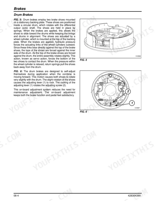
| Front Axle | 1139-1290 | Transmission, Final Drives, Brakes |
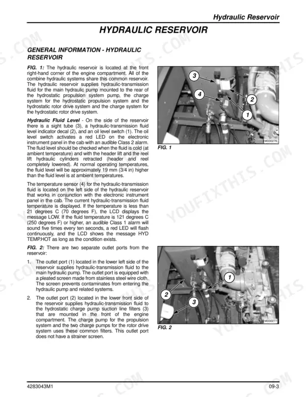
| Hydraulics | 1291-1742 | Hydraulic Control Valve, Hydrostatic Propel and Rotor Drive, Priming and Start-Up, Pump Tests, Hydraulic Schematics |
| Electrical | 1743-1914 | Wiring Schematics, Power Distribution, Grounds, Charging System, Starting System, Batteries |
| Electronics | 1915-2144 | Electronic Instrument Panel and Engine Trouble Codes, Console Controller Fault Codes, Header Height and Reel Drive Control Modules |
| Cab and HVAC | 2145-2374 | Cab, Air Conditioning, Heater, Blower, Windshield Wiper |
Quick Reference Specifications
| Specification | Value | Page |
|---|---|---|
| Engine model | C13, 6 cylinder in line, wastegate turbocharged and charge air cooled | p. 157 |
| Piston displacement | 12.5 liters (763 cu in) | p. 157 |
| Rated horsepower, Tier 3 | 317 kW (425 hp) @ 2100 rpm | p. 157 |
| Engine oil pressure at rated speed | 240 to 480 kPa (35 to 70 psi) | p. 157 |
| Fuel tank | 870.6 liters (230 gal) | p. 156 |
| Engine cooling system | 56.8 liters (15 gal) | p. 156 |
| Engine crankcase | 30.28 liters (8 gal) | p. 156 |
| Rotor gearbox | 4.0 liters (8.0 pt), SAE 85W-90 API-GL-5 | p. 156 |
| Hydraulic reservoir | 68.14 liters (18.0 gal), Permatran 821XL | p. 156 |
| Hydraulic system relief (pressure compensator) | 186.158 bar (2700 psi) | p. 160 |
| Hydrostatic propulsion pressure limiter | 449.88 bar (6525 psi) | p. 160 |
| Charging system voltage (12-volt system) | 13.5 - 14.5 volts, never above 15 volts | p. 1898 |
| Transmission mounting bolts torque | 217 Nm (160 lbf ft) | p. 223 |
Massey Ferguson 9895 Common Problems This Manual Covers
Unthreshed heads in the sample when cutting flax, clover or hard-threshing small grain
The crop is not threshing completely. The Threshing and Separating chapter has you fit concave blanks to the front concave sections. Add one blank at a time, starting at the front, and check the sample before you add the next one.
Manual Section: Threshing and Separating - Concaves and concave blanks p. 1045Hydraulic or hydrostatic pump cavitating at start-up after a repair
Stop the engine right away. Check the suction lines, the screen and the filters for leaks and correct the cause, then prime and bleed the system using the priming and start-up procedure. Charge pump pressure must be at least 689 kPa (100 psi) above case pressure.
Manual Section: Hydraulics - Priming and start-up p. 1479Hydraulic pump wearing out
Measure case drain flow using the pump tests in the Hydraulics chapter. If flow is above 11.4 liters (3 gal) per minute, the pump has to come off for repair. Testing first stops you from pulling a good pump in the middle of harvest.
Manual Section: Hydraulics - Pump tests p. 1638Undercharged battery or short bulb life
Put a meter on the charging system. It should read 13.5 - 14.5 volts and never go above 15 volts. Following the charging system section, check the wiring and terminals, the alternator belt tension and the battery state of charge.
Manual Section: Electrical - Charging system p. 1898Frequently Asked Questions
The instrument panel is showing engine trouble code 51 in yellow. What is it telling me?
Code 51 means system voltage is intermittent or erratic. Start with the charging system and the connections, not the engine. A healthy 12-volt system reads 13.5 - 14.5 volts and never goes above 15 volts. The electrical chapter also covers grounds and power distribution, so you can trace a bad connection wire by wire. p. 2020
Does this manual cover a full internal rebuild of the C13 engine?
No. The engine chapter covers the jobs you do on the engine in the combine: oil, fuel system, cooling system, air cleaner and the engine drive belt. You still get the C13 specs, including 12.5 liters (763 cu in) and 317 kW (425 hp) at 2100 rpm, Tier 3. Oil pressure at rated speed should read 240 to 480 kPa (35 to 70 psi). p. 157
What fluids, and how much, should I have on hand before a service?
The engine crankcase takes 30.28 liters (8 gal) and the cooling system 56.8 liters (15 gal). The hydraulic reservoir holds 68.14 liters (18.0 gal) of Permatran 821XL. The rotor gearbox takes 4.0 liters (8.0 pt) of SAE 85W-90 API-GL-5. The fuel tank holds 870.6 liters (230 gal). p. 156
What should the hydraulic and hydrostatic pressures read?
The hydraulic system relief at the pressure compensator is 186.158 bar (2700 psi). The hydrostatic propulsion pressure limiter is 449.88 bar (6525 psi). The hydraulics chapter has the pump test procedures and schematics, so you know which port to put the gauge on. p. 160
Are the torque values there for pulling and refitting the transmission?
Yes. The front axle chapter covers the transmission, final drives and brakes. The transmission mounting bolts torque to 217 Nm (160 lbf ft). For fasteners a procedure doesn't call out, use the standard and special torque tables in the specifications chapter. p. 223


Reviews
There are no reviews yet.