
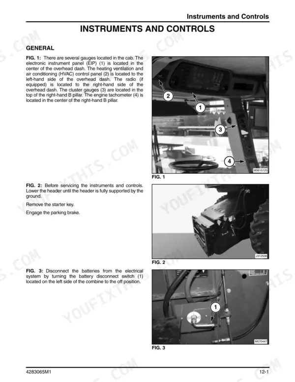
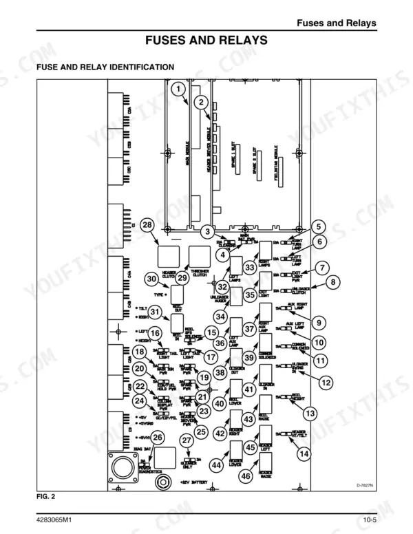
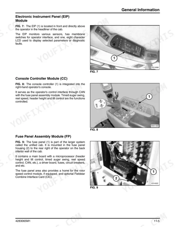
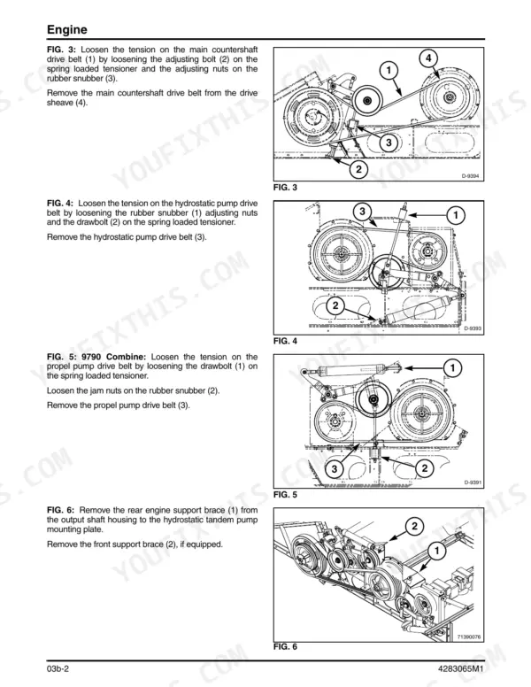
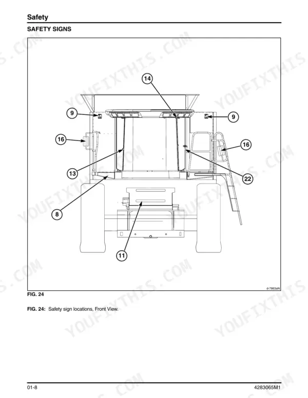
Massey Ferguson publication 4283065M1 is the factory workshop manual for the 9690 and 9790 combines. It runs 3,578 pages in 12 chapters, bound into one PDF. It covers specifications by serial number, load sense hydraulics with schematics, the hydrostatic rotor and propulsion drives, wiring diagrams for each subsystem and the Electronic Instrument Panel header diagnostics.
A combine parked in the shed with the crop still standing loses you a dry day every day it sits. This book gives you the charge pressures, case pressure limits, special torque values and the header fault parameters, so you can find the fault instead of guessing.
The engine depends on the serial number, so check the plate first; the specifications chapter lists each engine by serial range.
What's Inside This Massey Ferguson 9690, 9790 Manual
| System | Pages | Key Topics |
|---|---|---|
| General Information | 1-150 | Safety, Combine Identification, Lubrication and Maintenance, Storage, Torque Charts, Conversion Tables |
| Specifications | 151-328 | 9690 and 9790 Specification Sheets, Capacities, Engine Data by Serial Number, Hydraulic Pressures, Special Torque Requirements, Dimensions |
| Engine - Drives, Cooling and Fuel | 329-448 | Engine Removal and Installation by Serial Number, Engine Output Shaft, Radiator, Charge Air Cooler, Fuel Tank, Engine Drive Belts |
| Material Handling | 449-1082 | Feeder, Front Beater, Feeder Reverser, Stone Trap |
| Material Discharge | 1083-1212 | Grain Tank, Unloading Augers, Unloader Swing |
| Rear Axle | 1213-1350 | Steering Axle, Power Rear Wheel Drive |
| Threshing and Separating | 1351-1646 | Rotor, Rotor Gearbox, Concaves, Cleaning Fan, Shoe, Chaffer and Sieve |
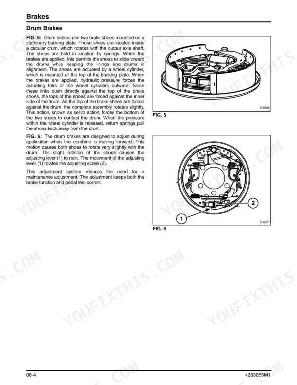
| Front Axle | 1647-1826 | Transmission, Final Drives, Brakes |
| Hydraulics | 1827-2574 | Load Sense Hydraulic System, Control Valve Stack, Hydrostatic Rotor and Propulsion Drives, Priming and Start-Up, Hydraulic Schematics |
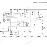
| Electrical System | 2575-3062 | Batteries, Power Distribution, Wiring Diagrams per Subsystem |
| Electronics | 3063-3310 | Electronic Instrument Panel, Header Diagnostics, Diagnostic Fault Parameters |
| Cab and HVAC | 3311-3578 | Cab Components, Air Conditioning and Heating |
Quick Reference Specifications
| Specification | Value | Page |
|---|---|---|
| Engine 9690 | Sisu 84CTA Tier III 8.4L from serial HR87101; Cummins QSC 8.3L prior to HR87101 | p. 155 |
| Rated power, 9690 Sisu 84CTA | 224 kW (300 hp) @ 2100 rpm | p. 168 |
| Rated power, 9790 Sisu 84CTA Tier 3 | 261 kW (350 hp) @ 2100 rpm | p. 245 |
| Fuel tank (9690 and 9790) | 605.6 liters (160 gal) | p. 167 |
| Engine crankcase, 9690 | 24.6 liters (6.5 gal) from HR87101; 18.9 liters (5 gal) prior to HR87101 | p. 167 |
| Hydraulic system complete, standard rear axle / power rear wheel drive axle | 90.8 liters (95.9 qt) / 97.6 liters (103.1 qt), Permatran 821XL | p. 168 |
| Hydraulic reservoir | 31.4 liters (33.2 qt) | p. 168 |
| Rotor gearbox | 4.0 liters (8.0 pt), SAE 85W-90 API-GL-5 | p. 167 |
| Hydraulic system relief (9690) | 18.61 MPa (2700 psi) | p. 173 |
| Hydrostatic propulsion / rotor pressure limiter (9690) | 44.98 MPa (6525 psi) / 48.26 MPa (7000 psi) | p. 173 |
| Hydrostatic case (drain) pressure | should not exceed 276 kPa (40 psi) | p. 2219 |
| Rotor nut (front of rotor) torque | 405 Nm (300 lbf ft) | p. 319 |
| Grain tank capacity (9690) | 10 570 liters (300 bu) | p. 158 |
Massey Ferguson 9690, 9790 Common Problems This Manual Covers
Hydraulic or hydrostatic pumps cavitate after a fluid change or hydraulic repair
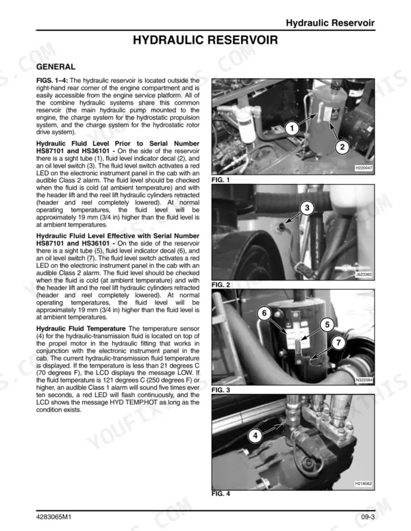
Shut the engine down right away and find the cause before you restart. The priming and start-up procedure in Chapter 09 Hydraulics has you check the suction lines, screen and filters for leaks. Then bleed the air at low idle. The reservoir alone holds 31.4 liters (33.2 qt) of Permatran 821XL.
Manual Section: Chapter 09 Hydraulics - Priming and Start-up p. 2214EIP shows HDR CTRL with HGT ERR or TILT ERR and the buzzer sounds
Hold the header height switch for at least five seconds to put the Electronic Instrument Panel into header diagnostic mode. Read the fault parameters listed in Chapter 11. Then trace the circuit on the matching subsystem wiring diagram in Chapter 10 before you replace any sensor or switch.
Manual Section: Chapter 11 Electronics - Header Diagnostics p. 3162Rotor or propulsion drive is weak or sluggish
Put gauges on the pumps before you replace anything. In neutral, the propel pump should show 2.7 to 2.9 MPa (392 to 420 psi) above case pressure. The rotor pump should show 2.3 to 2.7 MPa (335 to 385 psi). Case pressure must stay under 276 kPa (40 psi). Chapter 09 covers both hydrostatic drives.
Manual Section: Chapter 09 Hydraulics - Hydrostatic Rotor and Propulsion Drives p. 2230Rotor nut or axle bolts work loose after rotor or axle work
Use the special torque table in Chapter 02 Specifications, not the general torque chart. The rotor nut at the front of the rotor takes 405 Nm (300 lbf ft). Standard axle bolts take 285 Nm (210 lbf ft). Chapter 07 covers the rotor gearbox, which takes 4.0 liters (8.0 pt) of SAE 85W-90 API-GL-5.
Manual Section: Chapter 02 Specifications - Special Torque Requirements p. 319Frequently Asked Questions
Which engine specs apply to my 9690 or 9790?
It depends on the serial number, and the book keeps each engine separate. A 9690 from HR87101 on has the Sisu 84CTA Tier III 8.4L, rated 224 kW (300 hp) at 2100 rpm. Earlier 9690s carry the Cummins QSC 8.3L. On the 9790, the Sisu 84CTA starts at HR36101. Cummins QSL9 Tier III covers HP36101-HP36999, and QSL9 Tier II comes before that. p. 155
Why are the hydraulic pumps cavitating after I changed the fluid?
The usual cause is air or a suction-side leak. Stop the engine and fix the cause before you restart. Check the suction lines, screen and filters for leaks, then bleed the air at low idle. A full refill takes 90.8 liters (95.9 qt) of Permatran 821XL with the standard rear axle. With power rear wheel drive it takes 97.6 liters (103.1 qt). p. 2214
The EIP shows HDR CTRL with HGT ERR or TILT ERR and the buzzer is going. What now?
The header control system has found a height or tilt error. Hold the header height switch for at least five seconds to enter header diagnostic mode. Chapter 11 explains the fault parameters, and the subsystem wiring diagrams in Chapter 10 let you trace the circuit before you buy a sensor. p. 3161
The rotor or ground drive feels weak. What pressures should I see?
Check charge pressure first. In neutral, the propel pump should run 2.7 to 2.9 MPa (392 to 420 psi) above case pressure. The rotor pump should run 2.3 to 2.7 MPa (335 to 385 psi). Case pressure should not go over 276 kPa (40 psi). On a 9690, the propulsion pressure limiter is 44.98 MPa (6525 psi) and the rotor limiter is 48.26 MPa (7000 psi). p. 2230
Can I rebuild the engine with this manual?
No. Chapter 03b covers removing and installing both engine generations, plus the engine output shaft, radiator, charge air cooler, fuel tank and engine drive belts. For pistons, crankshaft or cylinder head work you need the Sisu or Cummins engine manual. For pulling the engine and setting it back in, this book has the procedure. p. 329
Reviews
There are no reviews yet.