
Part of the Case IH Repair Manuals.
Within the hour you could be splitting the hydrostatic pump on your 1460, and this Case IH 1440, 1460, 1480 service manual PDF puts the Eaton teardown in front of you: 864 pages of factory service data, OEM GSS-1479-B, covering all three Axial-Flow combines. The hydrostatic drive gets the longest treatment in the book, from principles through troubleshooting to pump and motor rebuilds, and hydraulic schematics trace the header lift and automatic header control circuits valve by valve. Wiring diagrams for the cab, shaft speed monitor, and air conditioning close out the electrical section. Torque the pulley retaining nut on the feeder jackshaft to 185 to 250 ft. lbs. and the rotor reluctance pickup lock nut to 35 to 40 ft. lbs., straight from the spec tables. Guess wrong on a rotor rebuild and the second teardown costs you a harvest day. Bookmarked and text searchable, it goes wherever the combine sits, shop or field edge.
What's Inside This Case IH 1440, 1460, 1480 Manual
| System | Pages | Key Topics |
|---|---|---|
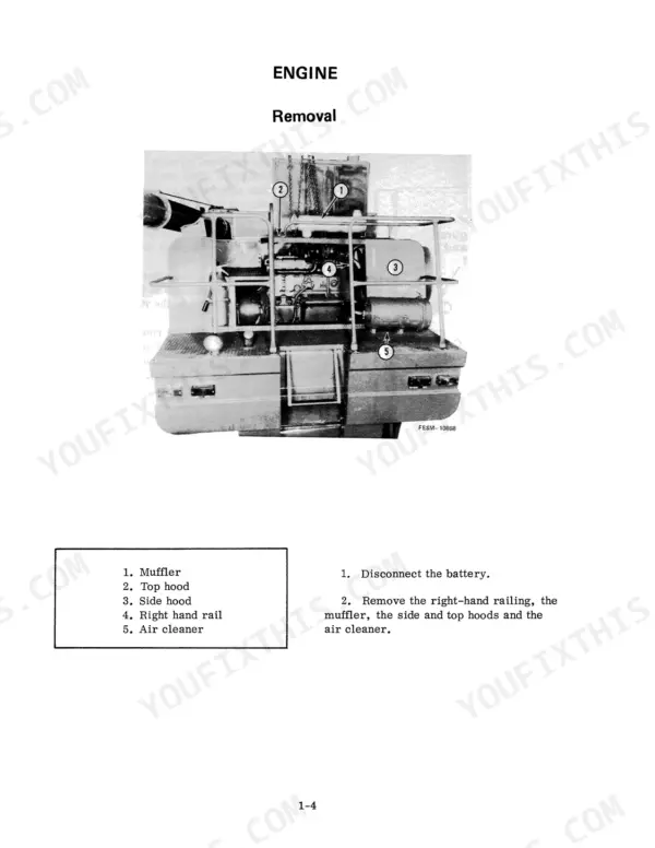
| Engine and Fuel Tank | 21-30 | Engine Removal, Engine Installation, Fuel Tank Removal |
| Separator Drive Units | 31-90 | Engine PTO Gear Box, Separator Drive Jackshaft Without Straw Chopper, Separator Drive Jackshaft with Straw Chopper |
| Hydrostatic Drive | 91-242 | Principles of Hydrostatics, Troubleshooting, Eaton Hydrostatic Pumps and Motors |
| Brakes, Transmission, Differential, Final Drives, Guide Wheels and Tracks | 243-398 | Transmission Change Gears, Transmission Removal and Disassembly, Brakes |
| Hydraulic System | 399-508 | Header Lift, Automatic Header Control, Hydraulic Pumps |
| Electro-Hydraulic System | 509-662 | Hydrostatic Power Steering, Electro-Hydraulic Control Valves, Accumulator |
| Cutting and Feeding | 663-670 | Feeder and Fan Jackshaft Drive Housing |
| Threshing and Separating | 671-712 | Rotor Drive Gear Case and Torque Sensing Unit, Rotor Removal, Auger Bed Assembly |
| Cleaning System | 713-720 | Cleaning Fan, Variable Speed Fan Drive |
| Elevators and Grain Tank | 721-732 | Grain Tank Unloader Vertical Auger, Elevator Drive Jackshaft, Grain Elevator and Distribution Auger |
| Operator's Cab and Electrical System | 733-864 | Servicing the Components, Air Conditioning System, Shaft Speed Monitoring System |
Quick Reference Specifications
| Specification | Value | Page |
|---|---|---|
| Standard Torque Data for Inch Nuts and Bolts (Type 1 Bolts 6" length or less, 1/4 diameter) | 6-7 ft-lb | p. 8 |
| Standard Torque Data for Inch Nuts and Bolts (Type 1 Bolts 6" length or less, 1 diameter) | 265-300 ft-lb | p. 8 |
| Pulley Retaining Nut | 250.67 - 338.75 N·m (185-250 ft. lbs.) | p. 663 |
| Rotor reluctance pickup lock nut torque | 47 to 54 N·m (35 to 40 ft. lbs.) | p. 694 |
| Sensor sprocket bolt torque | 237 N·m (175 ft. lbs.) | p. 695 |
| Shaker shaft nut torque | 68 N·m (50 ft. lbs.) | p. 699 |
| Unloader control cable pull | 178 N (40 lbs.) | p. 723 |
| Drive chain free movement | 25 mm (1 inch) | p. 731 |
| New spring length between washers | 171.45 mm (6-3/4 inches) | p. 730 |
| Engine-to-rail mounting bolts torque | 135.6-162.7 N·m | p. 22 |
| Separator drive clutch hydraulic system charge pressure | 620-758 kPa | p. 464 |
| Header lift system relief valve pressure | 12.07 MPa | p. 437 |
Case IH 1440, 1460, 1480 Common Problems This Manual Covers
Case IH 1460 rotor drive coupling breaks repeatedly, rotor stops under load in heavy crop
Inspect the rotor drive gear case and torque sensing unit before installing another coupling; a seized bearing or stuck torque sensor will shear new couplings fast. Check rotor bearings for roughness with the belts off. When reassembling the drive, torque the sensor sprocket bolt to 237 N·m (175 ft. lbs.) per page 695, and clear rotor jams before restarting.
Manual Section: Threshing and Separating p. 695Hydro slips under load, combine loses drive on hills or jumps out of gear
Check the hydro oil level and filter first. Test charge pressure, inspect the variable displacement motor, and note sluggish response in both ranges. Tighten any weeping 3/4 inch tube nuts on the 37 degree flared fittings to 77 to 82 ft. lbs. before condemning the pump. The troubleshooting chart on page 105 walks the low-charge-pressure and will-not-drive cases.
Manual Section: Hydrostatic Drive p. 105Chaffer and sieve shake violently side to side, sieves crack or linkage breaks
Replace the shaker arm rubber bushings and check the pitman and shaker shaft bearings for play before the sieve tears itself apart. Grab each arm and rock it; any slop means worn bushings. After fitting new bearings, torque the shaker shaft nut to 68 N·m (50 ft. lbs.), the spec on page 699, then run the separator empty.
Manual Section: Threshing and Separating p. 699Grain tank unloader quits or auger drive belt burns when tank is full
Check the unloader drive belt for glazing and replace it if cracked. Verify the engagement linkage pulls through fully; adjust the control cable so it applies 178 N (40 lbs.) of pull as specified on page 723. Clean packed grain out of the vertical auger housing before re-engaging, and never engage the drive at full throttle.
Manual Section: Elevators and Grain Tank p. 723Clean grain elevator chain jumps sprockets or slaps the housing in heavy corn
Measure chain tension at the midpoint of the longest span; allow no more than 25 mm (1 inch) of total free movement, per the adjustment on page 731. Set the tensioner spring to 171.45 mm (6-3/4 inches) between washers when new, page 730, and replace stretched chains and hooked sprockets as a set.
Manual Section: Elevators and Grain Tank p. 731Feeder chain stalls or slip clutch chatters and squeals in tough green stems
Test the feeder jackshaft slip clutch before blaming the chain. Without a rock trap, the clutch should slip at 610 to 746 N·m, the setting on page 668; with a rock trap installed use 881 to 1017 N·m from page 669. Reset a glazed clutch, then set feeder chain tension and check for bent slats.
Manual Section: Cutting and Feeding p. 668Frequently Asked Questions
How do you troubleshoot a loss of drive or hydraulic issues on a Case IH 1440 combine?
Troubleshooting a loss of drive involves checking the charge pressure and case pressure. If the system has very low or zero charge pressure, it may indicate a system low on fluid or a charge pump suction line/filter issue. If pressures are normal, check the control linkage to the pump or internal control valve linkage. Refer to the troubleshooting chart on page 105 for specific test readings and remedies. p. 105
What is the recommended torque for the engine-to-rail mounting bolts on a Case IH 1440/1460/1480 combine?
The recommended torque for the engine-to-rail mounting bolts is 135.6 to 162.7 N·m (100 to 120 ft. lbs.). p. 22
What is the correct procedure for checking the separator drive clutch hydraulic system pressure on a 1480 combine?
To check the separator drive clutch hydraulic system pressure, install a 14-1-4 300 psi gauge in the line between the electrical solenoid hydraulic valve and the separator clutch pack. Run the combine at high idle with the separator engaged for 10 minutes to warm the oil. The pressure should be between 210-235 psi. p. 32
What accumulator precharge does a Case IH 1440 combine need without automatic header control?
The accumulator is factory precharged to 6895 kPa (1000 psi). It is essential that the accumulator precharge not be lower than 500 psi when the grain or corn head is resting on the ground. p. 448
What is the specified backlash for the separator drive gear on a 1440/1460/1480 combine?
The correct backlash for the separator drive gear is from .102 mm to .203 mm (.004 in. to .008 in.). Adjust the shim pack until this dimension is established. p. 67
How will I receive this Case IH 1440 Service Manual?
A 864-page Service Manual in searchable PDF format, available the moment you complete checkout. View on computer, tablet, or phone, with no shipping wait.
Can I print this Case IH 1440 manual?
Yes. The PDF is DRM-free, so printing works from any reader and any printer.





Reviews
There are no reviews yet.