
Part of the Case IH Repair Manuals.
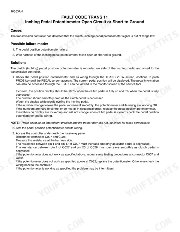
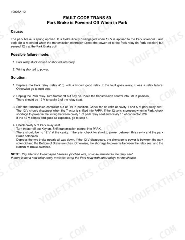
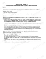
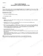
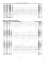
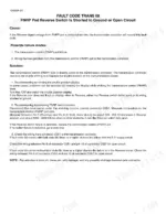
Fault codes on the armrest display mean nothing without the tree that decodes them, and the 195-page Case IH 330 service manual PDF (factory number 84257309) is that tree, written for the STX and Steiger Series tractors across two dozen model designations. Transmission, armrest, and instrumentation controller fault codes fill most of the book, each one running from symptom to connector pin to the reading that confirms the failure. Calibration routines for the inching pedal and transmission clutches sit up front, followed by neutral relay, BOC switch, and FNRP pod shuttle faults. Probe a transmission speed sensor and you should see about 3 k ohms at 20 degrees C; the hydraulic fan control circuit reads 5.1 to 7.5 ohms. A tractor parked on a code is acres not covered. Bookmarks and a live text layer put you on the exact fault code in seconds, so your tractor finishes the pass instead of sitting.
What's Inside This Case IH STX, Steiger 280–535 Manual
| System | Pages | Key Topics |
|---|---|---|
| Service Manual Title Page | 1 | STX Series Tractors, Steiger Series Tractors |
| Service Manual Publication List | 2 | Engine, Electrical, Steering, Power Train, Hydraulics, Chassis |
| Inching Pedal and Transmission Calibration | 7-12 | Inching Pedal Potentiometer, Transmission Clutch Calibration |
| Neutral Relay and BOC Switch Faults | 13-18 | BOC Switch, Neutral Relay, Park Brake |
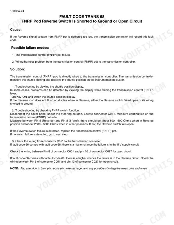
| FNRP Pod and Shuttle Control Faults | 19-31 | FNRP Pod, Forward Switch, Reverse Switch, Neutral Switch |
| Speed Sensor and Clutch Slippage Faults | 32-41 | Battery Voltage, Wheel Speed Sensor, Transmission Clutch Slippage |
| Clutch Solenoid Circuit Faults | 42-60 | Lube Solenoid, 2F Clutch Solenoid, 2R Clutch Solenoid, 1M Clutch Solenoid, 5F Clutch Solenoid, 1R Clutch Solenoid, 1F Clutch Solenoid, 4F Clutch Solenoid |
| Controller Configuration and Communication Faults | 61-86 | ICU Model Mismatch, Transmission Calibration, Armrest Controller Communication, Hydraulic Pressure Transducer, Backup Alarm |
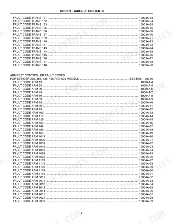
| Armrest Controller Fault Codes | 87-132 | Fault Code Arm 19, Fault Code Arm 29, Fault Code Arm 39, Fault Code Arm 49, Fault Code Arm 59, Fault Code Arm 69, Fault Code Arm 79, Fault Code Arm 89 |
| Instrumentation Controller Fault Codes | 133-195 | Fault Code Inst 1015, Fault Code Inst 1024, Fault Code Inst 1034, Fault Code Inst 1044, Fault Code Inst 3010, Fault Code Inst 3020, Fault Code Inst 3022, Fault Code Inst 5010 |
Quick Reference Specifications
| Specification | Value | Page |
|---|---|---|
| Hydraulic Fan Control Circuit Resistance | 5.1 to 7.5 ohms | p. 143 |
| Hydraulic oil temperature sensor resistance at 0 degrees F | 24K Ohms | p. 187 |
| Inching Pedal Potentiometer Voltage Range | 0 to 5 volts | p. 11 |
| Transmission Speed Sensor Resistance | 3 k ohms | p. 37 |
| Transmission Speed Sensor Resistance at 20°C | 3 k ohms | p. 41 |
| Lube Solenoid Resistance | 10 ohms | p. 42 |
| Clutch Solenoid Resistance | 10 ohms | p. 43 |
| Backup Alarm Resistance | 2 to 5 ohms | p. 86 |
| Throttle Potentiometer Resistance (Pins 1 to 3) | 2430 to 2570 ohms | p. 90 |
| Remote Hydraulic Flow Control Potentiometer Resistance | 205 to 295 ohms | p. 97 |
| Hitch Position Control Lever Potentiometer Resistance | 900 to 1100 ohms | p. 95 |
| Differential Lock Relay Coil Resistance | 80 ohms | p. 191 |
Case IH STX, Steiger 280–535 Common Problems This Manual Covers
Case IH Steiger 380 cranks but won't start, dash lights dim out during cranking
Check battery cable ends and the frame ground for corrosion before you condemn the starter. Clean both posts, then load test the batteries. If the dash drops out and communication faults follow, measure CAN bus terminator resistance at 120 ohms per the controller diagnostics starting on page 73 before replacing any controller.
Manual Section: Controller Configuration and Communication Faults p. 73Three-point hitch raises but drifts down or loses control after shutdown
Verify the hitch position control lever potentiometer first. Disconnect the armrest connector and measure across the pot: resistance on page 95 should read 900 to 1100 ohms through full lever travel. A dropout in that sweep fools the controller into commanding lower. If the pot checks good, pull and inspect the hitch hold valve.
Manual Section: Armrest Controller Fault Codes p. 95Remote hydraulics slow or dead on one circuit when another remote is loaded
Start at the armrest, not the valve stack. Measure the remote hydraulic flow control potentiometer at 205 to 295 ohms as listed on page 97. If it falls in range, check hydraulic oil temperature: a sensor reading 2916 to 3564 ohms at 68 degrees F confirms the circuit before you chase standby pressure.
Manual Section: Armrest Controller Fault Codes p. 97Transmission shifts harshly, slips under load, or throws clutch slippage faults in the field
Disconnect the suspect clutch solenoid and measure the coil. Page 43 calls for 10 ohms; anything open or shorted means a bad solenoid or chafed harness. Also check the transmission speed sensor at 3 k ohms, and recalibrate the inching pedal, verifying the potentiometer sweeps a clean 0 to 5 volts.
Manual Section: Clutch Solenoid Circuit Faults p. 43Hydraulic oil overheating, cooling fan runs slow or not at all on hot afternoons
Clean the cooler cores and screens first, then test the hydraulic fan control solenoid: 5.1 to 7.5 ohms at the connector on page 143. Out of range, replace it. If it passes, confirm the oil temperature sensor reads 276 to 324 ohms at 180 degrees F so the controller sees real temperature.
Manual Section: Instrumentation Controller Fault Codes p. 143Differential lock won't engage or drops out in wet field conditions
Pull the differential lock relay and measure the coil at 80 ohms as specified on page 191. Replace it if it reads open. Inspect the switch harness for chafe where it passes the front axle, and clean the ground stud. Fix it in the shop now, before you are stuck at the wet end of the field.
Manual Section: Instrumentation Controller Fault Codes p. 191Frequently Asked Questions
How do I clear a fault code on a Case IH Steiger?
To clear a fault code, you must first address the underlying issue described in the specific fault code section. For many codes, such as TRANS 24, you can clear the fault codes and perform the calibration procedure using the Service Tool. p. 12
What should I do if the transmission controller displays fault code 70?
Fault code 70 indicates that the battery voltage is too low for clutch solenoid operation. You should test the battery voltage, which should be around 12 to 14 volts, and check the alternator output, which should be above 14 volts at C077 - B+. p. 32
What is the transmission speed sensor resistance spec on a Case IH STX, Steiger 280-535?
The resistance for the transmission speed sensor should be approximately 3 k ohms at 20 degrees Celsius. If the resistance is not within this specified range, the sensor should be replaced. p. 41
What is the lube solenoid resistance specification on a Case IH STX, Steiger 280-535?
The lube solenoid resistance should be approximately 10 ohms. If the measured resistance is dramatically higher than this, the solenoid coil has failed open and must be replaced. p. 42
What is the resistance spec for the 1st remote hydraulic flow control potentiometer on a Case IH STX, Steiger 280-535?
The resistance between pin 1 and pin 2 of connector J2 should be between 205 and 295 ohms. If the resistance is outside this range, the second panel must be replaced. p. 97
How will I receive this Case IH 280 Service Manual?
You get a 195-page searchable PDF that downloads instantly after checkout. Open it on your laptop, tablet, or phone, and bring it right to the shop floor.
Is this Case IH 280 manual print-friendly?
Zero restrictions. The PDF is DRM-free. Print whatever sections you need to take out to the shop. Standard letter or A4 paper works.




Reviews
There are no reviews yet.