
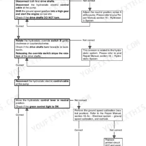
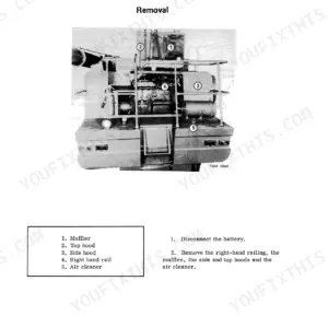
Part of the Case IH Repair Manuals.
When the torque amplifier quits pulling mid job and the nearest dealer is an hour away, you fix it yourself, and this Case IH 385 service manual PDF is the factory book for the work: 577 pages, OEM ID GSS-1416B, covering eleven utility tractor models from the 454 through the 84 Hydro and 385. Wiring diagrams map the electrical system, while hydraulic schematics trace the multiple control valve, the load and position control hitch, and the draft control cylinder valve assembly. Teardown coverage runs from front axle splits through the range transmission, hydrostatic drive, brakes, and independent PTO. Set tie rod ends to the steering knuckle arm at 68 to 100 N·m, and pull wheel nuts on thick discs to 109 to 135 N·m. Nobody is coming to help; it's you, the tractor, and daylight. Print what you need, let those pages take grease on the bench, and keep the bookmarked, keyword searchable file ready before the weather turns.
Complete the set for your 385, 454–884 Series and 84 Hydro
What's Inside This Case IH 385, 454–884 Series and 84 Hydro Manual
| System | Pages | Key Topics |
|---|---|---|
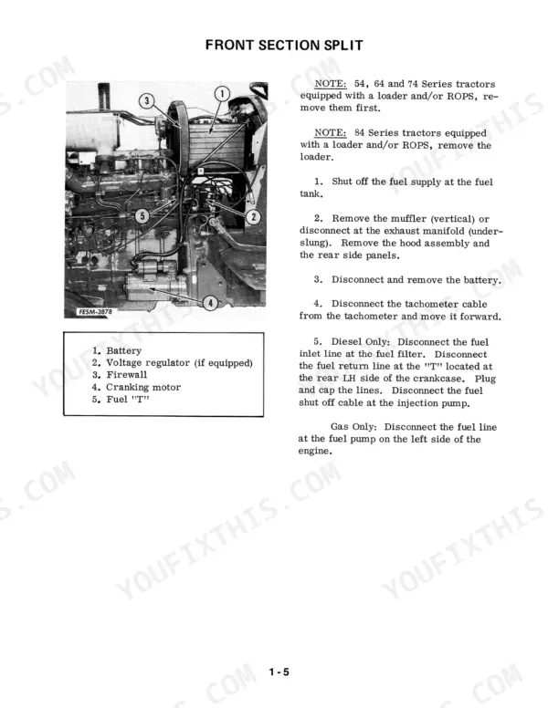
| ROPS - Loader - Tractor Splits | 26-49 | ROPS Protective Frame, Loader Removal, Front Section Split, Center Section Removal, Rear Section Split |
| Front End, Axle, and Wheels | 50-158 | Straight and Swept Back Front Axles, Steering Knuckle, Wheel Hub, Steering Cylinder, Kimco Front Drive Axle, Zf All Wheel Drive Axle |
| Steering | 159-194 | Power Steering, Steering Hand Pump Removal and Repair, Steering Linkage |
| Engine | 195-210 | Engine Removal |
| Fuel System | 211-214 | Fuel Tank |
| Electrical System | 215-234 | Specifications, Wiring Diagrams, Miscellaneous Electrical Information |
| Cooling System | 235-238 | Radiator |
| Clutch and Flywheel | 239-252 | Removal and Installation |
| Transmission | 253-440 | Clutch Housing and Speed Transmission, Range Transmission, Torque Amplifier, Hydrostatic Transmission |
| Differential | 441-458 | Rear Axle and Differential |
| Rear Axle, Housing, and Wheels | 459-474 | Rear Axle and Carrier Assembly, Planet Gear Assembly |
| Brakes | 475-494 | Brake Cylinders, Brake Discs and Pistons |
| Independent Power Take-Off | 495-512 | General, Disassembly, Inspection and Repair, Reassembly |
| Hydraulic System | 513-577 | Multiple Control Valve, Load and Position Control Hitch, Draft Control Cylinder Valve Assembly, Auxiliary Valves, Transmission Lubrication Pump |
Quick Reference Specifications
| Specification | Value | Page |
|---|---|---|
| Wheel nut torque (3.6 - 4.1 mm thick wheel disc) | 82 - 108 N·m (60 - 80 lbf ft) | p. 56 |
| Wheel nut torque (4.6 - 5.6 mm thick wheel disc) | 109 - 135 N·m (80 - 100 lbf ft) | p. 56 |
| Tie rod hex slotted nut torque | 28 - 94 N·m (20 - 70 lbf ft) | p. 56 |
| Tie rod end to steering knuckle arm torque | 68 - 100 N·m (50 - 75 lbf ft) | p. 58 |
| Cable retainer torque | 1.36 to 2.26 N·m (12 to 20 lbf-in) | p. 205 |
| Front governor control rod clearance | 3.048 mm (1/8 inch) | p. 206 |
| Pump mounting capscrews torque | 12-16 ft. lbs. | p. 523 |
| Transmission lubricating pump capacity | 4.5 gpm | p. 546 |
| Standard Torque for 1/4 inch Bolt (Type 1) | 5-6 ft-lbs | p. 11 |
| Standard Torque for 1 inch Bolt (Type 1) | 420-470 ft-lbs | p. 11 |
| Rear Axle Mounting Capscrew Torque | 170 ft-lbs | p. 48 |
| Axle Extension Bolts Torque | 246-272 ft-lbs | p. 54 |
Case IH 385, 454–884 Series and 84 Hydro Common Problems This Manual Covers
Case IH 484 hydraulic pump slipping, weak three-point hitch lift, loader will not hold a load
Drain the rear frame and pull the transfer pump intake screen before condemning the pump; a plugged screen starves it and wrecks the gears. Clean any rubber bushing debris out of the frame while it is open. If the pump comes off, torque the mounting capscrews to 12 to 16 ft. lbs. per page 523 on reassembly.
Manual Section: Hydraulic System p. 523Diesel starts, runs a few minutes, then slows to idle and dies in the field
Check the fuel shut-off cable first; a cable that creeps toward shut-off will starve the injection pump and mimic plugged filters. Adjust it per page 205 and tighten the cable retainer to 12 to 20 lbf-in. Then replace both fuel filters, crack the injector lines, and bleed the system until fuel runs clear with no air.
Manual Section: Engine p. 205Brake pedal goes to the floor after the tractor sits over winter, needs bleeding again
Bleed both circuits using the procedure in the brake section starting on page 475, then pressure test each brake piston assembly; a wheel cylinder that weeps overnight pulls in air every time the tractor sits. Replace leaking cylinders and lines instead of bleeding repeatedly. On the 484, 684, 784, 884, 84 Hydro, and 385, set pedal free height to 210 mm per page 487.
Manual Section: Brakes p. 487Hydro drive quits in both directions while the engine and hydraulic pump keep running
Test charge and system pressure with gauges before splitting the tractor; the relief valve should hold 2500 psi per page 516. If pressure is good but the tractor will not move, suspect a sheared drive shaft or coupler in the hydro box. Check the transmission oil for metal and pull the drive components for inspection.
Manual Section: Hydrostatic Transmission Troubleshooting p. 516Steering wanders and feels loose at road speed even after new tie-rod ends
Inspect the bolster pin and bushings before buying more tie-rod ends; play here mimics worn linkage. Jack the front end and rock each wheel to find the slop. Torque tie rod ends to the steering knuckle arms at 50 to 75 lbf-ft per page 58, and check the knuckle arm retaining bolts while you are under there.
Manual Section: Front End, Axle, and Wheels p. 58PTO clutch slips under load, baler flywheel slows down with the lever fully engaged
Test the IPTO lock up pressure before tearing into the clutch pack; it should hold 220 to 250 psi per page 506. Low pressure points to a leaking piston seal or worn valve, not burned discs. Verify the linkage gives full engagement travel, then pull the unit for inspection if pressure will not come up.
Manual Section: Independent Power Take-Off p. 506Frequently Asked Questions
What is the torque specification for the engine to front bolster bolts on 84 Series and 385 tractors?
For the 84 Series and 385 tractors, the engine to front bolster bolts should be torqued to 217 to 244 N·m (160 to 180 lbf-ft). p. 203
What is the torque spec for the axle mounting capscrews on the rear frame of a Case IH 454, 464, 484, 574, 674 tractor?
When installing the axle housings on the tractor, the mounting capscrews must be tightened to 170 ft. lbs. torque. p. 48
What is the wheel nut torque for a Case IH 385, 454-884 Series and 84 Hydro tractor with a 3.6-4.1 mm thick wheel disc?
For tractors equipped with a 3.6 - 4.1 mm (0.14 - 0.16 inch) thick wheel disc, the wheel nuts should be torqued to 82 - 108 N·m (60 - 80 lbf ft). p. 60
What is the hydrostatic transmission relief valve pressure spec for the Case IH 84 Hydro tractor?
The hydrostatic transmission system relief valve is set at 2500 psi. p. 516
What is the differential ring gear bolt torque spec for the Case IH 385, 454-884 Series and 84 Hydro tractors?
The ring gear mounting bolts should be torqued to 70 N·m (50 ft. lbs.). p. 119
How will I receive this Case IH 454 Service Manual?
All 577 pages arrive as one searchable PDF at checkout. Read it at the desk, then take the phone out to the machine.
Does this Case IH 454 manual allow printing?
Yes. It prints from any PDF reader, so run off the pages you need for your own repair work.





Reviews
There are no reviews yet.