
Part of the New Holland Repair Manuals.
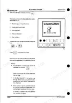
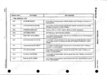
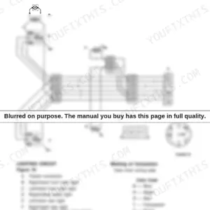
This 577-page New Holland TF76, TF78 repair manual PDF (OEM 604.64.016.00) is the factory service volume for both combines' drivetrain, hydraulics and electrics. Traction gearbox, brakes, final drives and steering axles start on page 15; the grain header with its knife and wobble box on page 55; the straw elevator on page 73; and the IVECO AIFO 8460 diesel with its injection pump and injectors on page 85. Wiring diagrams trace the starter circuit, engine throttle, reversing mechanism and unloading tube pin by pin across the CAN bus network, while the hydraulic and hydrostatic sections map the header height control valve and stack valves with every symbol explained. Calibration procedures for the header height electronic control and lateral float sensors keep your monitor honest through the season. Check the high pressure relief valve against its 160 bar setting, and refill the wobble box with 0.9 litres before the knife starts hammering. The serial number breakdown up front means you order the correct part the first time, and bookmarks plus a full text layer take you straight to the page.
What's Inside This New Holland TF76, TF78 Repair Manual
| System | Pages | Key Topics |
|---|---|---|
| Introduction | 3-14 | Explanation of Machine and Header Serial Numbers, Notes for Service Parts Catalogue Consulting, Conversion Chart, Tightening Torques |
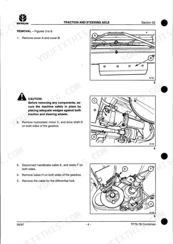
| Traction | 15-54 | Traction Gearbox, Brakes, Final Drives, Steering Axles |
| Grain Header | 55-72 | Reel Variator Adjustment, Knife and Wobble Box, Feed Auger, Slip Clutch |
| Straw Elevator | 73-84 | Straw Elevator Chain, Upper Shaft, Bottom Shaft |
| Engine | 85-94 | Fuel Injection Pump, Fuel Injectors, Cooling System |
| Airconditioning | 95-106 | Airconditioning Circuit, Ventilation Unit, Compressor Clutch Replacement |
| Hydraulic System | 107-164 | Hydraulic Components, Explanation of Symbols, Hydraulic Pump, Header Height Control Valve, Stack Valves, Hydraulic Cylinders |
| Hydrostatic System | 165-245 | Hydrostatic Circuit Diagrams, Hydrostatic Pump, Hydrostatic Motor |
| Electrical System Introduction and General Layout | 246-251 | Integrated Electrical System, CAN Network, Cab Nodes, Central Box Nodes, Engine Nodes |
| Data Communication and CAN Protocol | 252-256 | CAN Communication Protocol, Optical Fibre, Copper Wire, CAN Bus, Identifier Field, Data Field |
| Electrical Diagrams and Symbols | 257-274 | Wiring Diagram Standards, Colour Code, Wire Identification, Fuses, Electrical Symbols, Connector Pinouts |
| Location of Main Electrical Components | 275-296 | Printed Circuits, Monitors, Sensors, Limit Switches, Relays, Motors, Connectors, Valves |
| Electrical Diagrams for Specific Systems | 297-353 | Starter Circuit, Engine Throttle, Hydrostatic Drive, Powered Rear Axle, Reversing Mechanism, Unloading Tube |
| Reel Functions and Vertical Knives | 354-381 | Reel Speed, Reel Synchronization, Vertical Knives, Electrical Diagrams, Component Identification |
| Header Height and Lateral Float Control | 382-397 | Header Height Electronic Control, Lateral Float Sensors, Calibration Procedures, Electrical Diagrams |
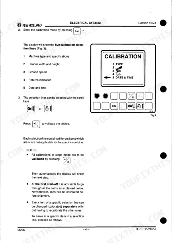
| Performance Monitor, Engine Gauges, and Air Conditioning | 398-564 | Performance Monitor, Engine Gauges, Dust Screen Brush, Air Conditioning, Software Update, Calibration Procedures |
| Pneumatic System | 565-575 | Circuit Diagram, Control Valves |
| Cab | 576-577 |
Quick Reference Specifications
| Specification | Value | Page |
|---|---|---|
| M6x1 plain torque | 5.8 Nm | p. 9 |
| Drive shaft speed | 575 rpm | p. 58 |
| Knife stroke | 76 mm | p. 58 |
| Nut E torque | 35 daNm | p. 76 |
| High pressure relief valve | 160 bar | p. 110 |
| Pressure relief valve | 200 bar | p. 110 |
| Traction Gearbox Oil Capacity | 15 litres | p. 16 |
| Final Drive Gearbox Oil Capacity | 6 litres | p. 40 |
| Wobble Box Oil Capacity | 0.9 litres | p. 58 |
| Transmission Main Shaft Nut Torque | 130 Nm | p. 27 |
| Brake Disc Nut Torque | 180 Nm | p. 38 |
| Final Drive Bolts G Torque | 650 Nm | p. 41 |
New Holland TF76, TF78 Common Problems This Manual Covers
New Holland TF76 grain header knife chatters and cuts ragged, wobble box noisy at full throttle
Check wobble box oil level first; capacity is 0.9 litres, and a dry box hammers the bearings. Verify drive shaft speed at 575 rpm against the spec on page 58. Replace worn knife sections and confirm the full 76 mm knife stroke after reassembling the wobble box per the grain header procedures.
Manual Section: Grain Header p. 58Header lifts slowly and unloading tube creeps, hydraulic pressure drops under load
Check the hydraulic oil level and the pump suction line for restriction before opening the system. Test the high pressure relief valve against its 160 bar setting on page 110. If pressure holds, trace internal leakage through the stack valves in the hydraulic section, torquing bolts 1 and 2 to 25 Nm on reassembly per page 138.
Manual Section: Hydraulic System p. 110Ground drive weak on hills and hydrostatic response sluggish once oil warms up
Check charge pressure first; low charge oil starves the closed loop once it warms. Verify the hydrostatic pump relief valve against its 420 bar setting on page 166. Drain, refill, and bleed following the hydrostatic start-up procedure, then recheck pressures before harvest. Replace the charge pump if pressure still sags hot.
Manual Section: Hydrostatic System p. 166Straw elevator chain jumping or rattling, crop feed surges between header and threshing drum
Check chain tension and slat condition with the elevator housing open. Retension the chain following the straw elevator procedure starting on page 73; a loose chain jumps sprockets in heavy, damp crop. If you pull the bottom shaft, torque nut E to 35 daNm during assembly as specified on page 76.
Manual Section: Straw Elevator p. 73Diesel engine hard starting, runs rough and smokes black under full threshing load
Check fuel filters and lines for restriction before blaming the pump. Verify injection pump timing and pre-stroke using the engine section procedures beginning on page 85. Test injectors for spray pattern and drip; torque injector mounting bolts to 21 Nm on reinstallation per page 90, then run the engine under load to confirm.
Manual Section: Engine p. 85Frequently Asked Questions
How do I clear an error code on the New Holland TF76 / TF78?
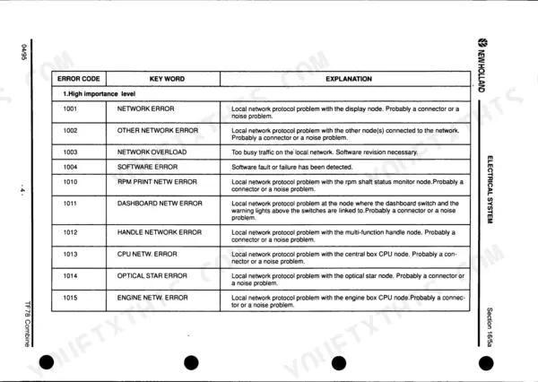
To clear error reports that appear when the ignition key is in the ON position before starting the engine, press the 'ESC' button or start the engine. For errors that occur after starting the engine, high priority errors are displayed continuously as long as the error exists, while medium priority errors remain on the screen for 5 seconds. p. 441
What is the torque specification for the transmission main shaft nut on the TF76 / TF78?
When assembling the transmission main shaft, the slotted nut 1 must be tightened to a torque of 130 Nm. p. 27
What is the oil capacity for the traction gearbox on the TF76 / TF78?
The traction gearbox has a capacity of 15 litres of AMBRA HYPOID 90 oil (ref. NH520A), which meets API GL5 or MIL-L 2105D specifications. p. 16
What is the correct valve clearance for the IVECO AIFO 8460 engine in the New Holland TF76 / TF78 combine?
The running valve clearance for the IVECO AIFO 8460 engine is 0.25 mm for intake valves and 0.50 mm for exhaust valves. p. 91
What is the injector calibration pressure for the IVECO AIFO 8460 engine on the New Holland TF76 / TF78?
The fuel injector test and calibration should be performed using tool 2 (Ref. IVECO 99301116), and the calibration value should be 280 +8 bar. p. 90
How is this New Holland TF76, TF78 Repair Manual delivered?
You download the Repair Manual yourself: 577 pages, searchable PDF, available immediately. Keep a copy on every device you use.
Is this New Holland TF76, TF78 manual print-friendly?
Yes. Print a single page or a chapter for your own shop use, on letter or A4.






Reviews
There are no reviews yet.