
Part of the New Holland Repair Manuals.
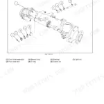
Knotter timing, feeder gear swaps, plunger alignment: on a D 1000 baler those jobs run on factory figures, and this 82-page New Holland D 1000 service manual PDF, OEM ID 40100030, is the one place they were printed. Hydraulic schematics trace the circuit from gear pump through control valve and relief valve to the pickup lift cylinder, while the road lights section maps wiring from tractor connector to rear lamps. Bale Command troubleshooting fills nearly a quarter of the book, walking you from each malfunction to its cause, and the feeder and plunger chapters end in full removal and refit procedures with the special tools named. Set needle to twine disc clearance at 3/16 inch (5 mm), and check the slip clutch at 5300 in. lbs. (599 N·m) before you condemn the driveline. A parked baler loses hay by the hour. The bookmarked, text-indexed PDF downloads in minutes and puts your machine back to tying.
What's Inside This New Holland D 1000 Manual
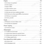
| System | Pages | Key Topics |
|---|---|---|
| Safety | 5 | PTO Drive Slip Clutch, Flywheel Brake, Shear Bolts |
| Drivelines | 6-8 | Flywheel, Hypoid Gearbox, Pickup, Stub Augers, Feeder System, Plunger, Knotter Shaft |
| Hitch Arrangement | 9 | Hitch Dimensions, Vertical Clearance |
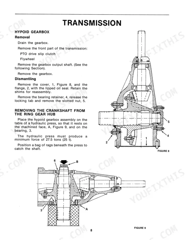
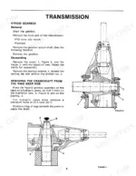
| Transmission | 10-16 | Hypoid Gearbox, Gearbox Output Shaft, Plunger Drive Crankshaft |
| Pickup | 17 | Pickup Guards, Guide Wheels, Wind Guard, Lift Cylinder, Flotation, Pickup Lift |
| Stub Augers | 18 | Drive Belt, Pickup Drive Chain, Pulley and Sprocket Assembly, Pickup Pivot Arm, Stripper Plate |
| Feeders | 19-33 | Operating Principle, Removing the Feeder, Replacing the Gears |
| Plunger | 34-37 | Removal of the Plunger, Preparation of the Plunger, Replacement of the Plunger |
| Knotters | 38-48 | Drive Shaft, Knotter Shaft, Adjustment of the Knotters |
| Central Knotter Lubrication | 49-51 | Piston Pump, Metering Units, Main Oil Way, Secondary Lines, Pump Stroke Adjustment |
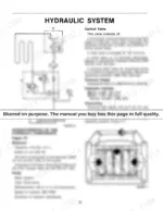
| Hydraulic System | 52-55 | Control Valve, Relief Valve, Pressure Gauge, Hydraulic Cylinder, Reservoir, Gear-Pump |
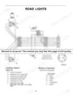
| Road Lights | 56 | Tractor Connector, Front Side Lights, Registration Plate Light, Rear Lights, Lighting Circuit |
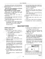
| Bale Command | 57-75 | Operating Principle, Malfunctions, Troubleshooting Mode |
| Specifications | 76-77 | Bale Chamber, Bale Weight, Driveline, Pickup, Infeed, Feeder, Plunger, Tying System |
| Special Tools | 78-79 | Flywheel Hook, Gearbox Removal Tool, Plunger Removal Hook, Large Sprocket Removal Tool, Feeder Removal Assembly, Feeder Tine Timing Gauge |
Quick Reference Specifications
| Specification | Value | Page |
|---|---|---|
| Slip clutch torque | 5300 in. lbs. (599 N·m) | p. 5 |
| Stripper Plate Adjustment | 5/32" ± 1/16" (4 mm ± 2) | p. 18 |
| Needle to twine disc clearance | 3/16 inch (5 mm) | p. 43 |
| Twine disc notch position | 1/32 inch to 1/16 inch (1 to 2 mm) | p. 43 |
| Flywheel shear bolt torque | 177 ft. lbs. | p. 5 |
| Plunger stroke | 540 mm | p. 7 |
| Hydraulic system relief valve range | 300-2250 PSI | p. 52 |
| Total weight | 9277 lbs. | p. 77 |
| Tire pressure | 36 PSI | p. 77 |
New Holland D 1000 Common Problems This Manual Covers
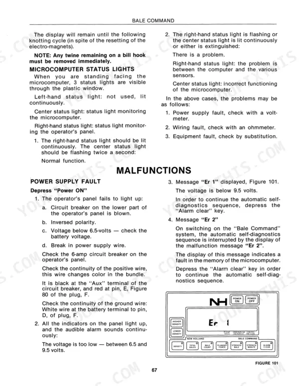
New Holland D1000 Bale Command flashes error codes, baler will only run in manual mode
Check the tractor power supply and connector before blaming the console. Match the displayed code against the Er 1 through Er 7 reference on page 69, then run troubleshooting mode to test each sensor in turn. Bad ties often trace to mechanical drift, so confirm needle to twine disc clearance holds 3/16 inch (5 mm) as well.
Manual Section: Bale Command Malfunctions p. 69Knotters miss ties or drop twine, bill hook leaves ragged ends on the bale
Verify needle drive timing before throwing parts at it: set the needle drive rod to 4-3/8 inch (110 mm) using the procedure on page 44. Check needle to twine disc clearance at 3/16 inch (5 mm) on page 43, and set the knife arm 3/8 to 1/2 inch (10 to 13 mm) from the bill hook tip.
Manual Section: Knotter Adjustments p. 41Pickup leaves strips of hay in the windrow, tines bent or missing
Inspect every tine bar with the pickup raised and the PTO shaft disconnected; replace bent or missing tines before they work loose and ride into the feeders. Check pickup flotation and guide wheel height on page 17, then set the stripper plate clearance to 5/32 inch (4 mm) as shown on page 18.
Manual Section: Pickup p. 17Centre bearing or gearbox running hot, growling noise under load in heavy crop
Check each 50mm self-locking bearing and the centre bearing for heat and play after the first hard run of the day. Inspect the hypoid gearbox pinion shaft and bearings for wear following the procedure starting on page 10. Rule out a slipping PTO clutch as the heat source; it is rated at 5300 in. lbs. (599 N·m).
Manual Section: Transmission Inspection p. 10Loud bang then baler stops feeding, shear bolt breaks every few bales
Replace the flywheel shear bolt and torque it to 177 ft. lbs. (240 N·m), locking tab secured, per page 5. Repeated failures mean the feeders are striking the plunger: install the feeder tine timing gauge shown with the special tools on page 78, retime the feeders, and verify timing before the next windrow.
Manual Section: Feeder Tine TimingFrequently Asked Questions
How do I reset the Bale Command system after an error code appears?
To clear error messages like 'Er 1', 'Er 2', 'Er 3', or 'Er 5', you must depress the 'Alarm clear' key on the operator's panel. This allows the automatic self-diagnostics sequence to continue. p. 69
What are the torque specifications for the flywheel shear bolt and feeder shear bolt on a New Holland D 1000 baler?
The flywheel shear bolt (Part No. 211824) is an M8 x 55, and the feeder shear bolt (Part No. 544502) is an M10 x 60. The manual specifies tightening the flywheel bolt (Z) to 177 ft. lbs. (240 N-m) and the bolt (U) to 66 ft. lbs. (90 N-m). p. 5
How do I perform an 'Auto 0' calibration for the Bale Command system?
Ensure the plunger is at front-dead-center. Switch on the panel, wait for self-diagnostics to finish, then depress the 'Density' key followed by the 'NH' key. Hold both until 'Auto 0' appears on the display. p. 70
What is the correct oil viscosity and capacity for the hydraulic system on a New Holland D 1000 baler?
The hydraulic system reservoir has a capacity of 14.8 quarts (14 liters) and requires SAE 90 grade oil. p. 52
What is the required torque for the gearbox mounting bolts on the New Holland D 1000 baler?
The six M16 bolts securing the gearbox to the mainframe must be tightened to a torque of 144 ft. lbs. (195 N-m). p. 13
How quickly can I access this New Holland D 1000 manual after buying?
One searchable PDF covering 82 pages, delivered instantly. No disc, no shipping, no waiting on the post.
Is this New Holland D 1000 manual print-friendly?
Yes. It prints from any PDF reader, so run off the pages you need for your own repair work.




Reviews
There are no reviews yet.