

Part of the New Holland Repair Manuals.
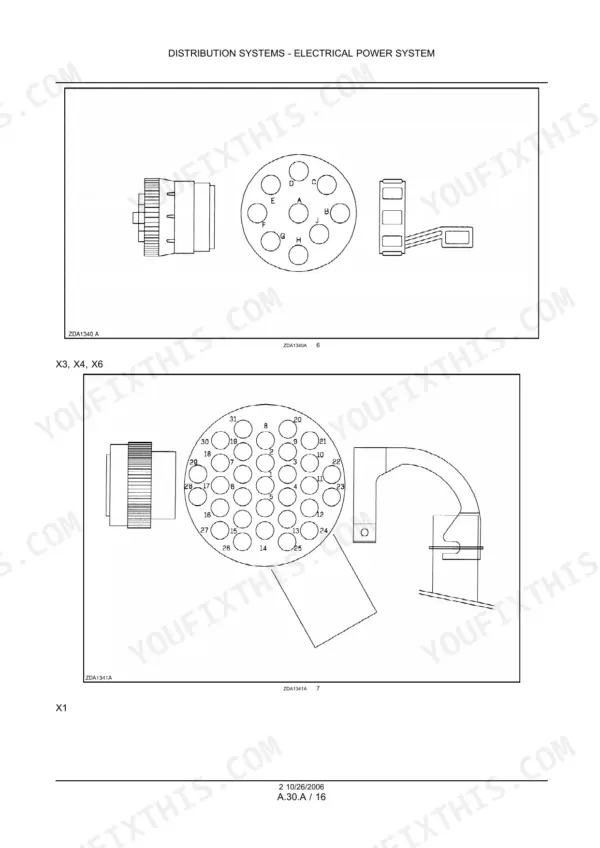
New Holland repair manual 87585143 covers the BB930A, BB940A, BB950A and BB960A big square balers one system at a time. It takes you through the PTO drive line, flywheel, main drive gearbox, pick-up, precompression and stuffer. The plunger, density system, knotters, bale ejector, crop cutter, packer and rotor feeding are covered the same way. You also get electrical schematic frames, connector diagrams and the monitor error code index, with an updated set from serial number 4500.
The knotter checks give the pinion to cam gear clearance, and the PTO section gives the flywheel slip clutch torque and spring length.
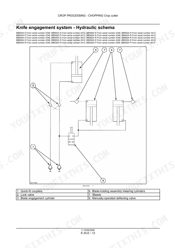
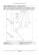
Troubleshooting tables list the cause and correction for each fault, and hydraulic schematics cover the density system, the bale chute and the knife engagement.
What's Inside This New Holland BB930A, BB940A, BB950A, BB960A Repair Manual
| System | Pages | Key Topics |
|---|---|---|
| Introduction, Specifications and Consumables | 1-26 | Model Variants, Contents, Safety Rules, Standard Torques, General Specifications for 4 and 6 Knotter Balers, Consumables, Serial Number Explanation |
| Electrical Power System and Schematics | 27-160 | Wiring Diagram Index and Symbols, Electrical Schematic Frames, Auxiliary Power Supply, Fuse and Relay Box, Connector Diagrams |
| Lighting System | 161-176 | Lighting Wiring Diagram, Electric Lights Static Description |
| Electronic System and Monitor | 177-236 | Electronic System Description, Error Code Index, Monitor Inputs and Outputs, Data Bus, Control Module Replacement, Troubleshooting |
| Oiling and Greasing Systems | 237-330 | Oiling System Specifications and Schematic, Automatic Greasing Distributors, Pump and Reservoir |
| Electrical System, Later Serial Numbers | 331-552 | Fuse Board, Alternator, Connector Diagrams 01 to 33, Electrical Schematic Frames 01 to 33 From Serial Number 4500, Diagnostics |
| Lighting, Electronic and Greasing Diagnostics | 553-616 | Lighting Troubleshooting, Error Code Index From Serial Number 4500, Monitor Troubleshooting, Greasing Distributor and Pump Diagnostics |
| PTO Drive Line and Flywheel | 617-672 | Flywheel Torque Limiter Torques and Spring Length, Constant Velocity Joint, Drive Shaft Removal and Overhaul, Flywheel and Flywheel Brake |
| Main Drive Gearbox | 673-732 | Gearbox Specifications and Torques, Shaft Shimming, Sections, Gearbox Removal, Disassembly, Assembly and Filling, Speed Sensor Diagnostics |
| Flywheel Brake Sensor Diagnostics | 733-744 | Flywheel Brake Sensor Error Codes |
| Parking Brake and Pneumatic Trailer Brake | 745-774 | Hub and Brake Shoe Removal and Installation, Pneumatic Trailer Brake Valve Specifications, Overhaul and Assembly |
| Axles and Shields | 775-796 | Single Axle and Tandem Axle Specifications, Protective Shields and Fenders |
| Pick-Up | 797-884 | Pick-Up Specifications and Crop Setting, Hydraulic Lift, Drum, Tines, Bearings, Drive Slip Clutch, Chains, Speed Sensor Diagnostics |
| Precompression and Stuffer | 885-936 | Precompression Chamber, Sensor Diagnostics, Stuffer Operation, Brake Check, Shaft Removal and Installation, Trip System |
| Bale Pressing and Density System | 937-1020 | Density System Specifications and Hydraulic Schematic, Density Cylinders, Valve and Pump, Plunger Clearances, Torques, Removal and Repair |
| Knotters and Twine Tying | 1021-1182 | Knotter System Specifications, Knotter Drive and Gearbox, Fans, Knotter Installation and Repair, Knotter Adjustments, Troubleshooting |
| Bale Ejector and Needle Protection | 1183-1234 | Bale Chute Specifications and Hydraulic Schematic, Ejector Cylinder and Valve, Troubleshooting, Needle Protecting System |
| Crop Cutter, Packer and Rotor Feeding | 1235-1296 | Crop Cutter Specifications, Knife Engagement Hydraulic Schematic, Valve and Cylinders, Packer Feeding Slip Clutch and Forks, Rotor Feeding |
| Stuffer Gearbox and Precompression Chamber | 1297-1338 | Stuffer Gearbox Filling, Removal, Disassembly, Assembly and Timing, Stuffer Replacement, Precompression Chamber, Troubleshooting |
| Pick-Up, Rotor, Stuffer and Cutter Diagnostics | 1339-1390 | Sensor Error Code Procedures for Pick-Up, Precompression, Rotor, Stuffer and Crop Cutter From Serial Number 4500 |
| Bale Density Diagnostics | 1391-1422 | Density System and Oil Pressure Sensor Error Code Procedures |
| Knotter and Twine Tying Diagnostics | 1423-1494 | Knotter Fans, Bale Length Control, Needle and Misstie Sensor Error Code Procedures |
| Bale Ejector Diagnostics | 1495-1514 | Bale Ejector Sensor Error Code Procedures, Ejector Schematic |
Quick Reference Specifications
| Specification | Value | Page |
|---|---|---|
| Main drive gearbox oil | 20 L 5.3 US gal, API GL5 | p. 25 |
| Stuffer drive gearbox oil | 3.75 L 1.0 US gal, API GL5 | p. 25 |
| Knotter drive gearbox oil | 2.75 L 0.7 US gal, API GL5 | p. 25 |
| Bale density hydraulic tank capacity | 4 L 1 US gal when levelled | p. 945 |
| Bale density control valve range | 0 to 160 bar (0 - 2320 psi), proportional valve | p. 948 |
| Bale density hydraulic pump | 3.8 cc rev at 743 RPM | p. 945 |
| Bale ejector relief valve | 150 bar 2175 psi | p. 1192 |
| Pick-up hydraulic lift, maximum required pressure | 190 bar 2755 psi | p. 808 |
| Plunger speed | 42 strokes/min | p. 946 |
| Plunger stroke length | 710 mm 27.952 in | p. 946 |
| Flywheel slip clutch torque | 1200 Nm (885 lbf.ft) 4 Knotter Standard and Packer; 1400 Nm (1032 lbf.ft) 4 Knotter Rotor Cutter; 1600 Nm (1180 lbf.ft) 6 Knotter Rotor Cutter | p. 625 |
| Flywheel slip clutch spring length | 46.4 mm 1.826 in 4 Knotter Standard and Packer; 45.4 mm 1.787 in 4 Knotter Rotor Cutter; 44.4 mm 1.748 in 6 Knotter Rotor Cutter | p. 625 |
| PTO speed | 1000 RPM | p. 20 |
| Main drive crank tightening screws torque | 785 - 833 Nm 4 Knotter; 735 - 784 Nm 6 Knotter | p. 680 |
| Knotter pinion to cam gear clearance | 0.15 - 0.40 mm 0.006 - 0.016 in, check after the first 400 bales then every 2,000 bales | p. 1101 |
| Knotter frame preload | 67 - 98 Nm 15 - 22 lb ft to swing each knotter | p. 1101 |
| Twine tensioner pull force | 10 - 12 kg 22 - 27 lb upper; 12 - 14 kg 27 - 31 lb lower | p. 1103 |
| Packer or rotor feeder slip clutch torque | 2100 Nm (1549 lb ft) Standard; 4000 Nm (2950 lb ft) 4 Knotter Packer Cutter; 6500 Nm (4795 lb ft) Rotor Cutter | p. 19 |
| Bale size, width x height | 800 mm (31.5 in) x 900 mm (35.43 in) 4 Knotter; 1200 mm (47.25 in) x 700 mm (27.5 in) 6 Knotter | p. 19 |
| Packer feeding drive chain tension | 20 mm 0.750 in deflection with 100 N 22 lb force | p. 1273 |
New Holland BB930A, BB940A, BB950A, BB960A Common Problems This Manual Covers
Knots hanging on the billhook
Usually there is not enough bottom twine tension, so increase the bottom twine tension first. If the knots still hang, the twine holder spring tension is too low. Tighten the twine holder spring adjusting bolt. The Knotters and Twine Tying troubleshooting table covers both causes next to the knotter adjustments.
Manual Section: Knotters and Twine Tying p. 1146No pressure inside the bale density circuit
First check that the manual valve is closed. Next check the oil level in the tank and whether the filter is clogged. If all of that checks out, the pump may be faulty. On the monitor, look for active errors in the Service mode. The Bale Pressing and Density System section has the hydraulic schematic, valve and pump procedures.
Manual Section: Bale Pressing and Density System p. 1011Incorrect pick-up blockage or pick-up slip messages on the monitor
Start with the pick-up speed sensor B8 and check its adjustment. If the sensor cannot be adjusted, replace it. The Pick-Up section covers the speed sensor diagnostics. The Pick-Up, Rotor, Stuffer and Cutter Diagnostics section has the error code procedures from serial number 4500.
Manual Section: Electronic System and Monitor p. 220Bale ejector system failure
Check that the quick-fit couplers are correctly connected and put the tractor control valve lever in delivery. Tractor pressure must be over 150 bar 2175 psi. Clean the uni-directional flow reducer. If the relief valve is stuck or faulty, repair or replace it. The Bale Ejector and Needle Protection section has the hydraulic schematic and troubleshooting.
Manual Section: Bale Ejector and Needle Protection p. 1213Frequently Asked Questions
Does this manual cover my New Holland BB930A, BB940A, BB950A or BB960A big baler?
Yes, as long as your baler is one of the variants on the title page. Manual 87585143 lists BB930A P, R and S, BB940A P, R and S, BB950A R and S, and BB960A R and S. Updated electrical schematics and diagnostics start at serial number 4500. Check the serial number on the machine plate on the drawbar before you pick a wiring frame. p. 3
How much oil do the BB930A to BB960A main drive, stuffer and knotter gearboxes take?
The main drive gearbox takes 20 L 5.3 US gal. The stuffer drive gearbox takes 3.75 L 1.0 US gal and the knotter drive gearbox takes 2.75 L 0.7 US gal. All three run on API GL5, changed once a year. p. 25
What are the New Holland BB930A–BB960A plunger speed, stroke, bale size and density system pressure?
The plunger runs at 42 strokes/min with a 710 mm 27.952 in stroke. 4 knotter balers make a bale 800 mm (31.5 in) wide by 900 mm (35.43 in) high. 6 knotter balers make a bale 1200 mm (47.25 in) wide by 700 mm (27.5 in) high. The proportional density control valve works from 0 to 160 bar (0 - 2320 psi) and is fed by a 3.8 cc rev pump. p. 946
What are the New Holland BB930A–BB960A PTO speed and flywheel and feeder slip clutch settings?
PTO speed is 1000 RPM. The flywheel slip clutch is set at 1200 Nm (885 lbf.ft) on the 4 Knotter Standard and Packer. It is 1400 Nm (1032 lbf.ft) on the 4 Knotter Rotor Cutter and 1600 Nm (1180 lbf.ft) on the 6 Knotter Rotor Cutter. The packer or rotor feeder slip clutch is 2100 Nm (1549 lb ft) on Standard balers. It is 4000 Nm (2950 lb ft) on the 4 Knotter Packer Cutter and 6500 Nm (4795 lb ft) on Rotor Cutter balers. p. 625
What is inside this manual: wiring diagrams, hydraulic schematics, error codes, troubleshooting?
It has electrical schematic frames and connector diagrams for both serial number blocks. There are hydraulic schematics for the density system, the bale chute and ejector, and the knife engagement. The monitor error code index gives a procedure for each code. Troubleshooting tables cover the electronics, density system, knotters, ejector and stuffer. p. 58




Reviews
There are no reviews yet.