
Part of the New Holland Repair Manuals.
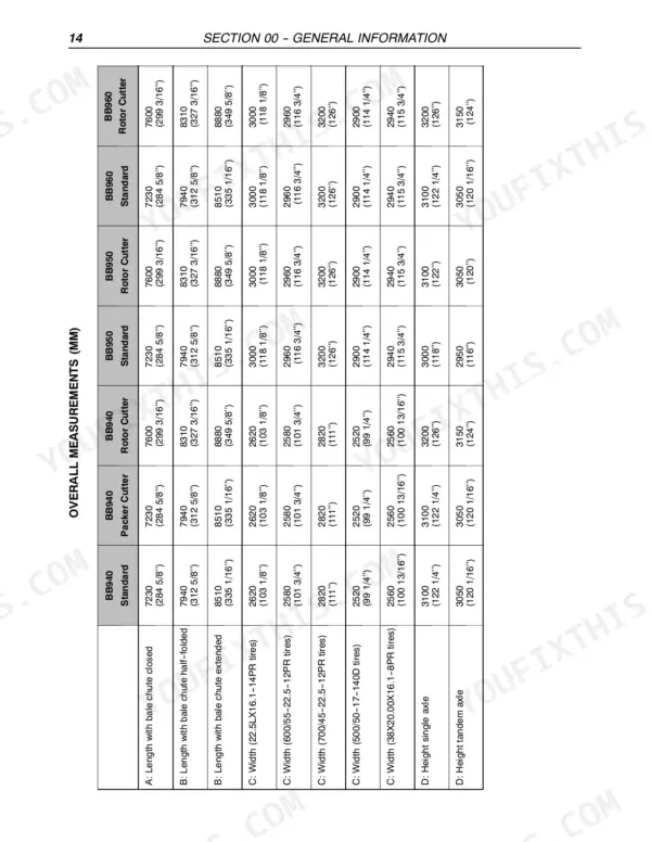
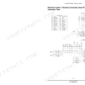
Every one of the 982 pages in this New Holland BB940, BB950, BB960 Repair Manual PDF (OEM #87028440) is aimed at the big square baler line, from the PTO driveline to bale ejection. Inside: factory wiring diagrams for the density system, knotter fan, and mistie indication circuits, plus hydraulic schematics for bale density, pick-up lifting, and blade control. You also get InfoView error code listings, knotter troubleshooting charts, and step-by-step main gearbox teardown and assembly procedures. Set the relief valve at 150 bar, torque the hydraulic pump screws to 10-15 Nm, and check roller chain tension at 20 mm of deflection under 100 N of force. A mistied bale costs you twine, time, and hay on the ground. Bookmarked cover to cover; search any spec by keyword and get back to baling.
Other edition of this manual
- New Holland BB940, BB960 Big Baler Repair Manual Original price was: $56.99.$39.99Current price is: $39.99.
What's Inside This New Holland BB940, BB950, BB960 Repair Manual
| System | Pages | Key Topics |
|---|---|---|
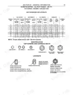
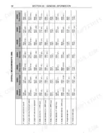
| General Information | 19-48 | Introduction, Important Information, Spare Parts, Safety Regulations, Explanation of Machine Serial Numbers, Units of Measure - Conversion Chart |
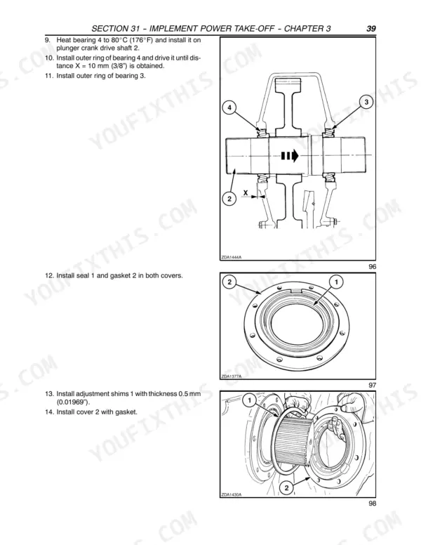
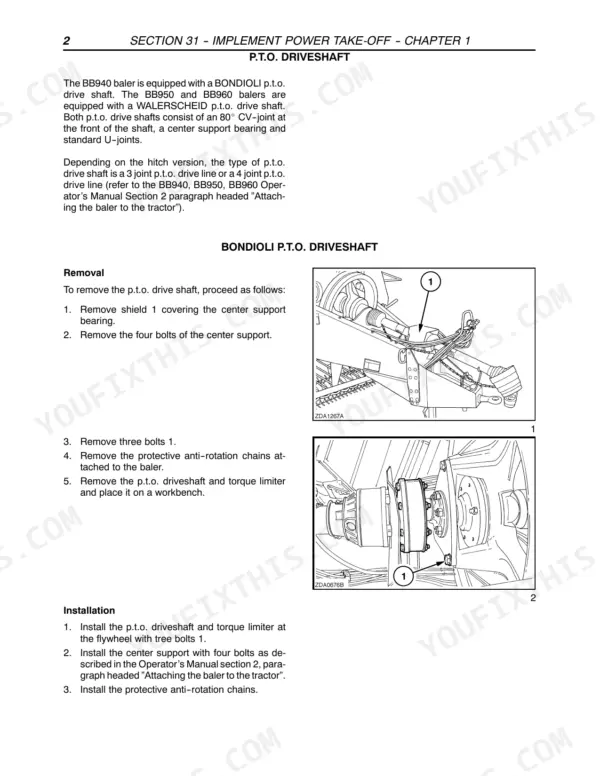
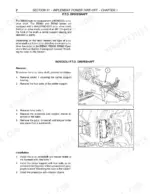
| Implement Power Take-Off | 49-128 | P.T.O. Drive Shaft (Walterscheid P.T.O. Driveshaft, Cv U-Joint, Standard U-Joint, Center Support Bearing Replacement, Flywheel Slip Clutch) |
| Brakes and Controls | 129-150 | Brake Shoe - Removal, Brake Control Shaft - Rep., Brake Shoe - Installation, Air Brake Valve, Operation, Technical Data, Disassembly - Assembly |
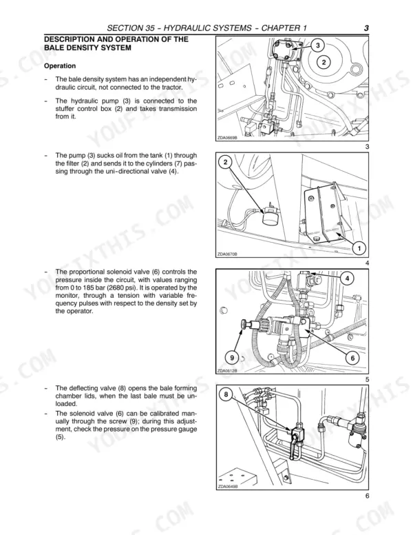
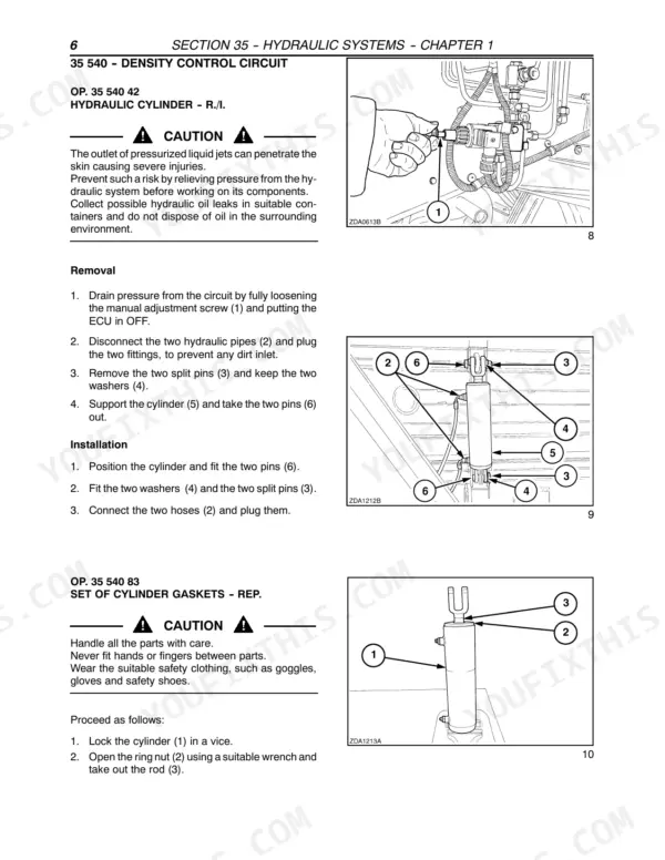
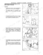
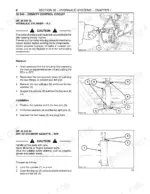
| Hydraulic Systems | 151-354 | Bale Density (Technical Data, Component Sketch and Location, Description and Operation, Troubleshooting, Hydraulic Cylinder - R./I., Set of Cylinder Gaskets - Rep., Proportional Solenoid Valve - R./I., Hydraulic Pump - R./I.) |
| Axles and Wheeels | 355-362 | Tire, Wheel, Wheel Hub, Bearing, Axle Assembly, Leaf Springs |
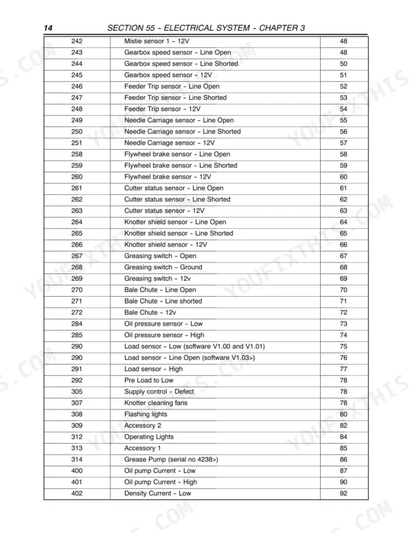
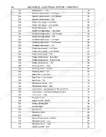
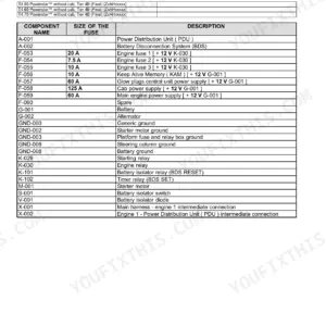
| Electrical System | 363-642 | General (Component Discription / Location, Printed Circuits, Sensors, Lighting, Fuses and Relays, Motors, Switches, Solenoids, Harnesses and Connections, Symbols, Connectors, Connector Location) |
| Product Feeding | 643-800 | Pickup (Specifications, Operation, Removal and Installation, Slip Clutch Repair, Burnishing the Slip Clutch, Driveshaft Bearing Replacement, Right Pivot Bearing Replacement, Left Pivot Bearing Replacement, Auger and Bearing Replacement, Gauge Wheel Bearing Replacement, Guard Replacement, Teeth Replacement, Tooth Bar and Tooth Bar Bearing Replacement, Cam Bearing Replacement, Cam Replacement, Right Reel Bearing Replacement, Left Reel Bearing Replacement, Reel Shaft Replacement, Cylinder Repair, Height Adjustment, Flotation Adjustment, Tine Repair, Windguard Height Adjustment) |
| Pressing | 801-832 | Plunger and Connecting Rods (Specifications, Tightening Torques, Clearances, Operation, Plunger R./I., Front Connecting Rod Bearing Replacement, Rear Connecting Rod Bearing Replacement, Plunger Vertical Bearing Replacement, Plunger Horizontal Bearing Replacement, Knife Clearance, Knife Sharpening) |
| Tying/Wrapping | 833-964 | Knotter General Information (Specifications, Operation, Troubleshooting, Knotter Trip Mechanism, Knotter Operation Overview, Knotter Operation Detail, Knotter Adjustments) |
| Ejection | 965-982 | Bale Discharge Chute, Bale Ejector, Plunger Rail, Side Hay Dogs, Density Cylinder Linkage, Compression Plate |
Quick Reference Specifications
| Specification | Value | Page |
|---|---|---|
| Hydraulic system pressure range | 0 to 185 bar (2680 psi) | p. 153 |
| Hydraulic pump fastening screws torque | 10-15 Nm (7.4-11 lbf.ft) | p. 159 |
| Pick-up lifting circuit max. pressure | 190 bar (2755 psi) | p. 161 |
| Relief valve calibration | 150 bar (2175 psi) | p. 179 |
| Roller chain tension | 20 mm (3/4") deflection with 100 N (22 lbs.) force | p. 650 |
| Packer slip clutch torque (without cutter) | 2100 N⋅m (1550 ft lbs) | p. 705 |
| Packer fork bearing clearance | 0.5mm (0.020″) | p. 709 |
| Plunger horizontal bearing nut torque | 200 N·m (147 ft. lbs.) | p. 829 |
| Plunger knife to stationary knife clearance | 3 mm (0.120") | p. 829 |
| Needle protection linkage minimum clearance | 1 mm | p. 853 |
| Needle-to-plunger timing overlap | 40 mm | p. 853 |
| Knife arm travel clearance | 15 mm | p. 853 |
New Holland BB940, BB950, BB960 Common Problems This Manual Covers
New Holland BB940 baler knotter mis-ties, bales drop with broken or loose twine knots
Check twine tension first: the upper run should pull at 10-12 kg (22-27 lbs.) and the lower at 12-14 kg (27-31 lbs.), both listed on page 854. If knots still slip, reset the knotter frame preload to 67-98 Nm (15-22 ft. lbs.) per page 852. Inspect the billhook and twine disc for nicks before condemning needles.
Manual Section: Knotter Troubleshooting p. 854Needles clunk or strike the plunger during needle rise, timing off after linkage service
Verify needle-to-plunger timing before anything else: the needle tip roller should sit 0 to 40 mm (0 to 1-9/16 in.) from the plunger knife tip, shown on page 947. Check the needle protection linkage holds at least 1 mm clearance per page 853, then set twine finger-to-needle clearance to 2-3 mm (1/16 to 1/8 in.).
Manual Section: Knotter Troubleshooting p. 947Bale density circuit has no pressure, bales come out loose and mis-shaped
Test the density circuit with a gauge and compare readings against the 0 to 185 bar (2680 psi) working range on page 153. Follow the no-pressure diagnosis starting, then inspect the proportional solenoid valve and cylinder gaskets for internal leakage. Never let system pressure exceed 190 bar (2755 psi).
Manual Section: Bale Density TroubleshootingStuffer drive shearbolt shears repeatedly, packer finger clutch slips in heavy windrows
Measure packer fork bearing clearance; anything past 0.5 mm (0.020 in.) lets the forks drift out of time with the stuffer, spec on page 709. Test the packer slip clutch and reset it to 2100 N·m (1550 ft lbs) per page 705. Fit correct-grade shearbolts only, never substitute harder bolts to stop the shearing.
Manual Section: Product Feeding p. 709Drive chains rattle and jump sprockets, pickup bounces and slams on uneven ground
Measure chain tension at mid-span: correct deflection is 20 mm (3/4 in.) under 100 N (22 lbs.) of force, spec on page 650. Replace any chain that stays loose after adjustment and inspect sprocket teeth for hooking. Set pickup flotation to 23 to 34 kg (50 to 75 lbs.) lift effort using the procedure on page 645.
Manual Section: Product Feeding p. 650Frequently Asked Questions
What are the torque specifications for the crank tightening screws on the BB940 baler?
The tightening torque for the crank tightening screws on the BB940 baler is 785 to 833 Nm (579 to 615 ft.lbs). p. 86
What is the correct torque for the wheel nuts on the baler?
The wheel nut torque for the baler is 305-332 Nm (224-247 lbs/ft). p. 73
How do I adjust the twine holder spring tension on the knotter?
When making an adjustment to the twine holder, do not turn the adjustment bolt more than 1/4 turn at a time. The twine drop length from the twine holder should be a minimum of 15 mm (9/16") long when the adjustment is correct. p. 86
What is the required torque for the packer slip clutch?
The packer slip clutch is factory set to 2100 N⋅m (1550 ft. lbs.). p. 136
What is the correct clearance for the knives to the stationary knife?
The clearance between the plunger knives and the stationary knife should be 3 mm (1/8"). p. 97
Do I get instant access to this New Holland BB940 Repair Manual?
A single searchable PDF file of 982 pages, downloadable right after payment. Nothing ships, nothing waits in the mail.
Can I print this New Holland BB940 manual?
Yes. Print the pages you need for the job in your own shop, and bin them when they get greasy.





Reviews
There are no reviews yet.