
Part of the New Holland Repair Manuals.
New Holland wrote part number 47851949 for the Tier 4B Final L218 and L220, May 2015 onward. It settles the numbers no video or parts counter will hand you: hydrostatic pump assembly bolts at 87 - 117 N·m (64 - 86 lb ft) with LOCTITE 243, belt deflection of 5 mm (13/64 in) under 5 kg (11 lb).
Guessing has a price on these machines. A drive pump pulled on a hunch, a second teardown after the leak comes back, a chain case run dry because nobody knew it holds 7.4 l (7.9 US qt) per side.
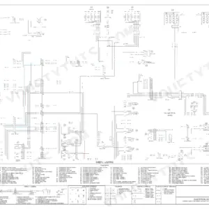
Engine, hydrostatic drive, main control valve, chain drive, electrical fault codes and three schematic posters are all in here. Download it once and it stays yours for as long as the loader does.
Other edition of this manual
What's Inside This New Holland L218, L220 Manual
| System | Pages | Key Topics |
|---|---|---|
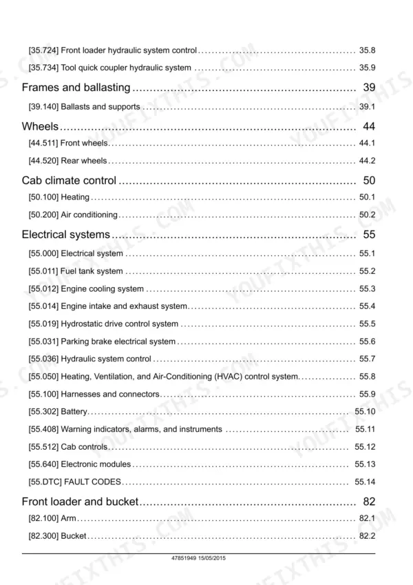
| Contents | 3-7 | |
| Introduction | 8-43 | |
| Engine | 44-83 | Engine and Crankcase, Engine Cooling System, Fan and Drive, Biodiesel Fuel Specifications, Engine Serial Number Locations |
| Power Coupling | 84-91 | Pump-Drive Assembly |
| Front Axle System - 25 | 92-113 | Chain Drive System |
| Rear Axle System - 27 | 114-135 | Chain Drive System, Transmission |
| Hydrostatic Drive | 136-263 | Hydrostatic Transmission, Two-Speed Assembly, Mechanical Control, Pump and Motor Components |
| Brakes and Controls - 33 | 264-275 | Parking Brake or Parking Lock |
| Hydraulic Systems | 276-457 | Fixed Displacement Pump, Reservoir, Cooler, And Filters, Main Control Valve, Auxiliary Hydraulic Valves, High Flow Hydraulics |
| Frames and Ballasting - 39 | 458-467 | Ballasts and Supports |
| Wheels - 44 | 468-479 | Front Wheels, Rear Wheels |
| Cab Climate Control - 50 | 480-543 | Heating, Air Conditioning |
| Electrical System | 545-600 | Fuel Tank System, Engine Cooling System, Engine Intake and Exhaust System, Hydrostatic Drive Control System, Parking Brake Electrical System, Hydraulic System Control |
| Harnesses and Connectors | 601-954 | Wiring Harnesses, Electrical Schematic Sheet |
| Battery | 955-966 | |
| Warning Indicators, Alarms, and Instruments | 967-1006 | Warning Indicators, Alarms, Instruments, Cab Controls, Electronic Modules |
| Fault Codes | 1007-1565 | DTC |
| Front Loader and Bucket - 82 | 1566-1609 | Arm, Bucket |
| Platform, Cab, Bodywork, and Decals - 90 | 1610-1636 | Cab, Cab Doors and Hatches |
| Special Tool Index | 1637-1640 | |
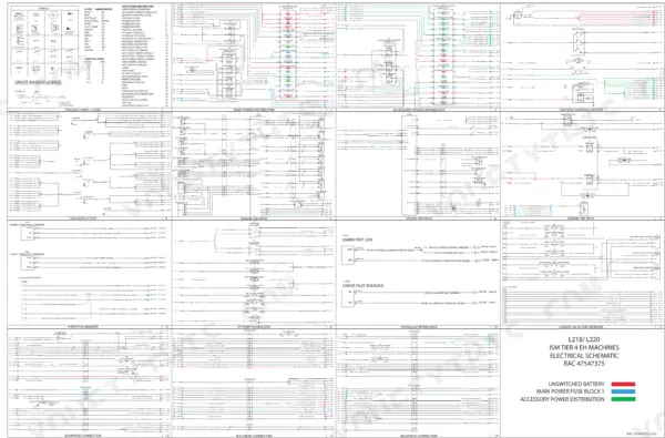
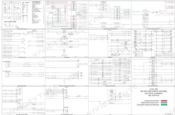
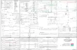
| Electrical Schematic Poster - 47547375 | 1641-1643 | |
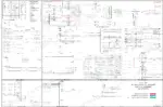
| Electrical Schematic Poster - 47547376 | 1644-1645 | |
| Hydraulic Schematic Poster - 47886242 | 1646-1653 |
Quick Reference Specifications
| Specification | Value | Page |
|---|---|---|
| Engine Coolant Temperature Alarm Threshold | above 110 °C (230 °F) | p. 35 |
| Fuel Tank Capacity | 60.5 l (16.0 US gal) (L213, L216) / 75.5 l (20.0 US gal) (L218, L220, L221, C227) / 95.5 l (25.5 US gal) (L223, L225, L230, C232, C238) | p. 39 |
| Cooling System Capacity | 15.6 l (4.2 US gal) (L213, L216) / 15.6 l (4.2 US gal) (L218, L220) / 17.0 l (4.5 US gal) (L221, C227) / 19 l (5 US gal) (L223, L225, L230, C232, C238) | p. 39 |
| Hydraulic System Reservoir Capacity | 15.0 l (3.96 US gal) | p. 39 |
| Hydraulic System Total Capacity | 29.2 l (7.7 US gal) (L213, L216) / 38.1 l (10.0 US gal) (L218, L220, L221, C227) / 45.3 l (12.0 US gal) (L223, L225, L230, C232, C238) | p. 39 |
| Chain Compartments Capacity (each side) | 6.25 l (6.6 US qt) (L213, L216) / 7.4 l (7.9 US qt) (L218, L220, L221) / 22.2 l (23.5 US qt) (L223, L225, L230) | p. 39 |
| Engine Oil Drain Plug Torque | 68 - 82 N·m (50 - 61 lb ft) | p. 47 |
| Hydrostatic Pump Assembly Bolts Torque | 87 - 117 N·m (64 - 86 lb ft) | p. 58 |
| Front Engine Mount Bolts Torque | 163 - 176 N·m (120 - 130 lb ft) | p. 58 |
| Belt Tension Deflection | 5 mm (13/64 in) with 5 kg (11 lb) force | p. 63 |
| Hydrostatic Main Relief (all ports) | 345 bar (5000 psi) | p. 1647 |
| Hydrostatic Charge Relief | 25 bar (360 psi) | p. 1647 |
New Holland L218, L220 Common Problems This Manual Covers
Hydraulic leaks that return weeks after the repair
Chase the joint, not the drip. The Hydraulic systems chapter walks the reservoir, cooler and filters, the main control valve and the auxiliary hydraulic valves, so a wet frame rail traces back to its real source. The manual also sets hose, connection and gasket inspection at every 3 months or 150 hours, which catches a weeping fitting before it empties the 38.1 l (10.0 US gal) system.
Manual Section: Hydraulic systems - reservoir, cooler and filters / main control valve p. 39Drive motors go slow after 20 to 30 minutes of heavy work
Heat and lost charge pressure feel identical from the seat. Hydrostatic drive covers the transmission, the two-speed assembly, the mechanical control and the pump and motor components, with the pressure checks that separate a weak charge circuit from a motor that is bypassing. Power coupling covers the pump-drive assembly behind it. Hydrostatic pump assembly bolts reinstall at 87 - 117 N·m (64 - 86 lb ft) with LOCTITE 243.
Manual Section: Hydrostatic drive / Power coupling - pump-drive assembly p. 58Repeat starter failures and burned battery cable ends
A starter that dies twice usually has a connection problem feeding it. Electrical systems covers the battery and the electronic modules, and the Engine install procedure sets the alternator positive battery cable nut at 4 N·m (35 lb in), which is easy to overtighten. Belt tension is set at 5 mm (13/64 in) of deflection under 5 kg (11 lb). The electrical schematic posters trace the charging and starting circuits.
Manual Section: Electrical systems - battery / Engine - engine and crankcase p. 62Chain case oil ignored until the drive turns noisy
Chain compartments stay quiet right up until they are not. Each side holds 7.4 l (7.9 US qt) of AMBRA SUPER GOLD 10W-30 on the L218 and L220, and the Front axle system and Rear axle system chapters cover the chain drive on each side. Check the level before chasing a drive complaint, because a low chain case grinds in wear that no hydraulic adjustment will undo.
Manual Section: Front axle system / Rear axle system - chain drive p. 39Frequently Asked Questions
My lift arms creep down overnight. What do I check first?
Settling means fluid is passing internally, at the lift cylinder pistons or through the main control valve spools. The Hydraulic systems section covers the main control valve, the fixed displacement pump and the auxiliary hydraulic valves, so you isolate the circuit before you buy anything. A drift test with the cylinder ports capped tells you cylinder or valve. Hydraulic schematic poster 47886242 shows which line feeds what. One avoided cylinder reseal covers the cost of the book.
The temperature gauge climbs and the machine gets slow under load. Is the pump going?
Read which bar graph is climbing first. Both engine coolant and hydraulic fluid read 0 - 110 °C (32 - 230 °F) and alarm above 110 °C (230 °F). If hydraulic oil is the hot one, start at the reservoir, cooler and filters, not the pump. Cooling system capacity is 15.6 l (4.2 US gal) on the L218 and L220. The Engine cooling system and Hydrostatic drive chapters cover the fan drive and the charge pressure checks. p. 39
How do I read and clear a fault code on an L218 or L220?
Electrical systems carries the fault code list along with the electronic modules that set them. You pull the code, find it in the table, then run the listed checks instead of swapping parts at the counter. Codes generally drop out once the fault is actually repaired and the key is cycled. A code that comes straight back is telling you the repair missed. Posters 47547375 and 47547376 give the wiring behind each circuit.
Low oil pressure warning on an early machine. Pump or sensor?
Work the cheap end first: level, viscosity, filter condition. The Capacities table on page 39 gives the crankcase fill with a filter change and the AMBRA UNITEK MASTERGOLD SBL CJ-4 spec. Engine and crankcase covers the oil pan access plate, whose bolts go to 42 - 58 N·m (31 - 43 lb ft). Confirm with a mechanical gauge before condemning the pump or the sensor. p. 61
The loader shuts off when I shift in the seat. Bad seat switch?
Usually the seat switch or the belt switch dropped out of circuit, and the interlock did its job. Vibration, chafed leads and a tired connector are the common causes. Electrical systems covers the interlock wiring and the module reading it, and the schematic posters let you backprobe the correct pin. Repair the switch rather than bypassing it, since that same interlock locks out drive and loader functions when you leave the seat.




Reviews
There are no reviews yet.