Part of the New Holland Repair Manuals.
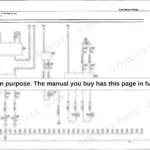
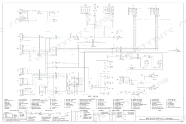
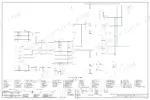
Wheel end off the axle housing, planetary carrier on the bench: the 825-page New Holland LW 170.B service manual pdf, OEM 6-49712, is written for the wheel loader job you are starting this hour. Schematic foldouts close out the book, mapping power control and distribution, lighting circuits, transmission controls and the full hydraulic circuit. Troubleshooting with pressure checks repeats through steering, power train, brakes and hydraulics, so a soft lift or a lazy loader control valve gets traced to a reading instead of a hunch. Removal and installation procedures reach the bucket cylinders, coupler solenoid locking valve and ride control accumulator. Set the main relief valve at 248 to 252 bar (3596 to 3654 psi); pull the planetary carrier locknut to between 700 and 1000 Nm (516 to 737 lb-ft). Every hour that loader sits in the yard, nobody is billing. Bookmarked and searchable, bought once and yours for as long as you own the machine.
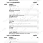
What's Inside This New Holland LW 170.B Manual
| System | Pages | Key Topics |
|---|---|---|
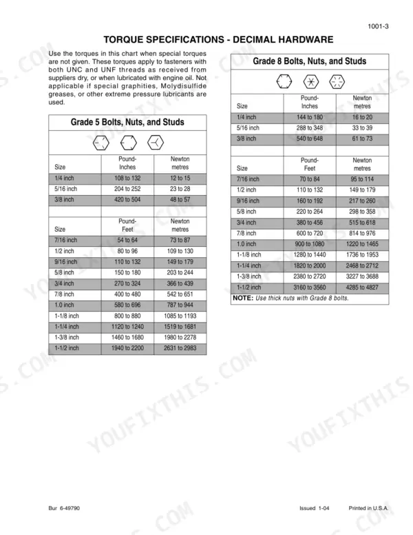
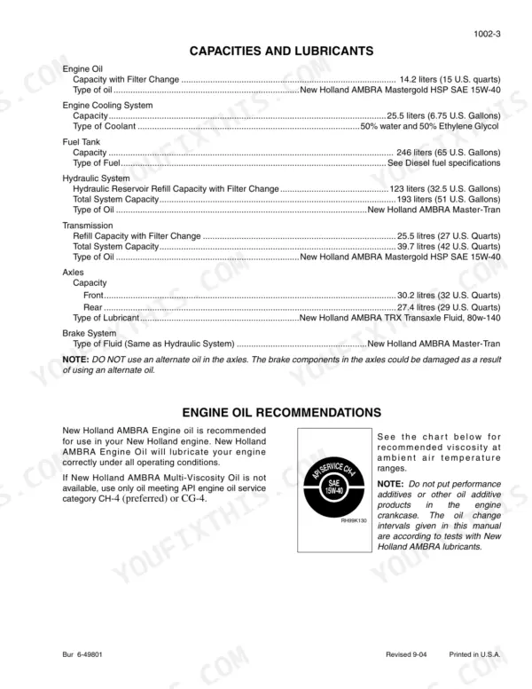
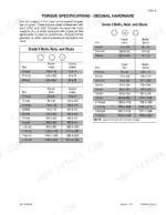
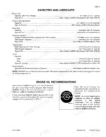
| General | 5-22 | Section Index - General, Standard Torque Specifications, Fluids and Lubricants, Metric Conversion Chart |
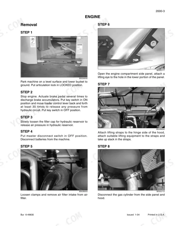
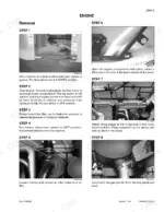
| Engines | 23-56 | Section Index - Engines, Engine and Radiator Removal and Installation, Stall Tests, After Cooler, Engine |
| Fuel System | 57-208 | Engine Service Manual, Main Engine Features |
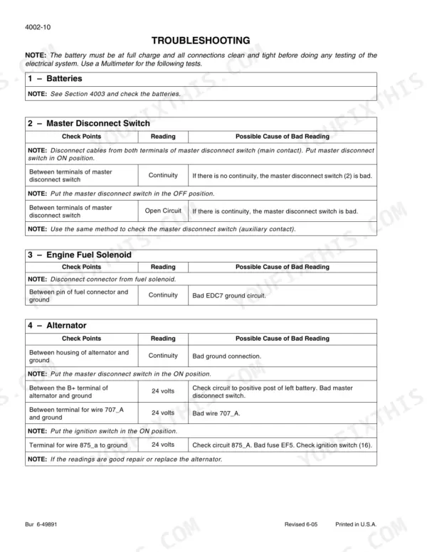
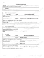
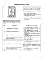
| Electrical | 209-332 | Section Index - Electrical, Removal and Installation of Starter and Alternator, Electrical Specifications and Troubleshooting, Batteries, Information and Diagnostic Center |
| Steering | 333-390 | Section Index - Steering, Removal and Installation of Steering Components, Steering Specifications, Pressure Checks, And Troubleshooting, Steering Control Valve |
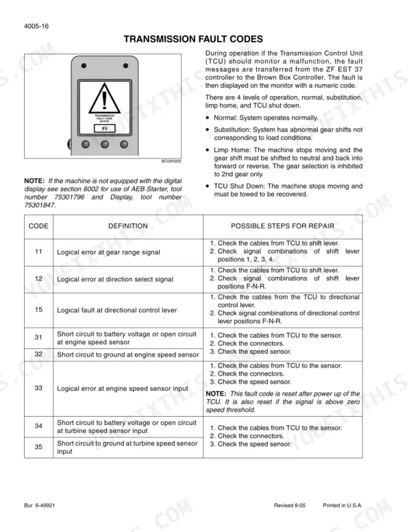
| Power Train | 391-588 | Section Index - Power Train, Removal and Installation of Power Train Components, Transmission Specifications, Pressure Checks, And Troubleshooting, Transmission, Front Axle |
| Brakes | 589-610 | Section Index - Brakes, Removal and Installation of Brake Components, Hydraulic Brake Troubleshooting, Parking Brake |
| Hydraulics | 611-732 | Section Index - Hydraulics, Removal and Installation of Hydraulic Components, Hydraulic Specifications, Troubleshooting, And Pressure Checks, Cleaning the Hydraulic System |
| Mounted Equipment | 733-818 | Section Index - Mounted Equipment, Air Conditioning Troubleshooting and System Checks for Systems with HFC-134a Refrigerant, Air Conditioner System Service |
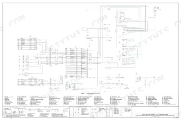
| Electrical Schematic Foldouts and Hydraulic Schematic Foldout | 819-825 | Power Control and Distribution, Lighting Circuits, Transmission Controls, Instrument Cluster, Machine Controls, Hydraulic Schematic |
Quick Reference Specifications
| Specification | Value | Page |
|---|---|---|
| Bolts Securing Wheel End to Axle Housing | 390 Nm (288 lb-ft) | p. 521 |
| Locknut Securing Planetary Carrier | 700 to 1000 Nm (516 to 737 lb-ft) | p. 519 |
| Drive Pinion Rolling Torque | 1.1 to 2.3 Nm (9.7 to 20.3 lb-inch) | p. 521 |
| Seal Caps Depth in Differential Housing | 1.5 to 2.5 mm (0.06 to 0.10 inch) | p. 521 |
| Main relief valve pressure settings LW 170.B | 248 to 252 bar (3596 to 3654 psi) | p. 683 |
| Circuit relief valve pressure setting Auxiliary A and B port | 290 bar (4206 psi) | p. 683 |
| Engine Oil Capacity with Filter Change | 14.2 liters | p. 15 |
| Engine Cooling System Capacity | 25.5 liters | p. 15 |
| Fuel Tank Capacity | 246 liters | p. 15 |
| Hydraulic System Total Capacity | 193 liters | p. 15 |
| Engine Mounting Bolts Torque | 244 to 298 Nm | p. 34 |
| Drive Shaft to Engine Coupling Bolts Torque | 53 to 62 Nm | p. 34 |