
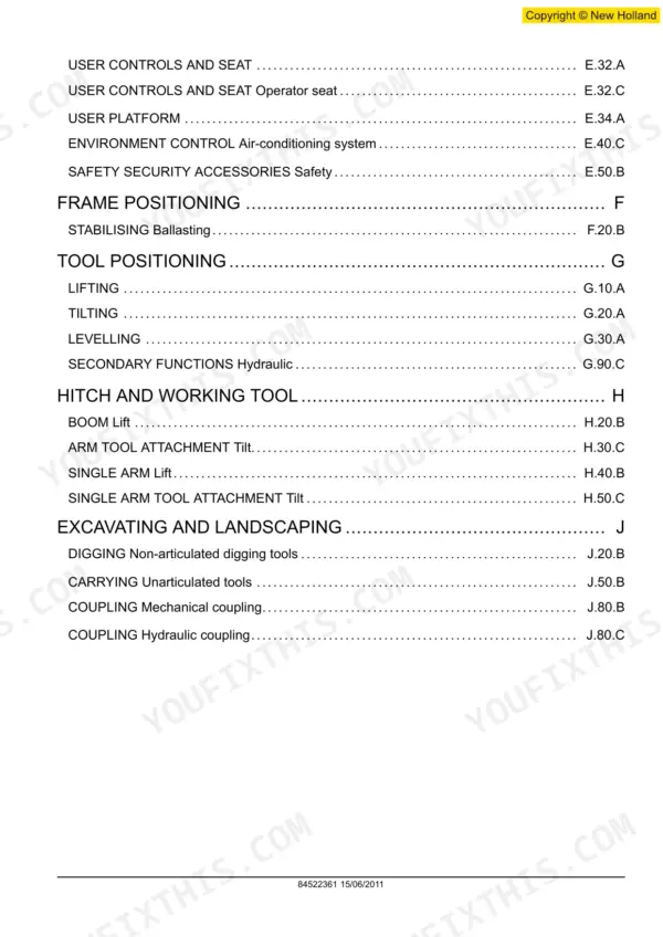
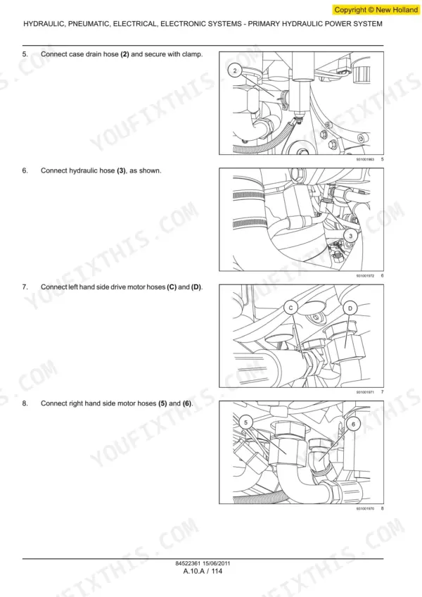
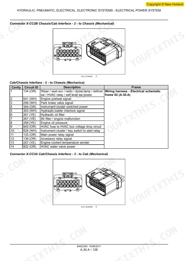

Part of the New Holland Repair Manuals.
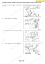
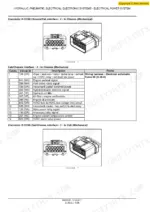
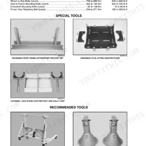
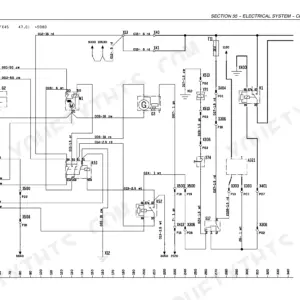
This is the factory repair manual for the New Holland 200 series skid steer and compact track loaders: the L213, L215, L218, L220, L223, L225 and L230 wheeled skid steers and the C227, C232 and C238 compact track loaders. It is organised the way CNH builds the machine rather than by chapter number, so the hydraulic, electrical and electronic systems come first and take about two thirds of the book, then the engine, the hydrostatic drive, the axles and brakes, the frame and cab, and the loader itself. The hydraulic chapters give the real pump numbers and relief settings, and the electrical chapters carry separate schematic frames for the mechanical and the electro-hydraulic control builds.
Other editions of this manual
- New Holland L221 L228 C227 C232 Tier 4B Service Manual $49.95
- New Holland L218, L220 Service Manual — Wiring Diagrams Original price was: $59.95.$39.95Current price is: $39.95.
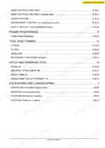
What's Inside This New Holland 200 Series (L213-L230, C227-C238) Repair Manual
| System | Pages | Key Topics |
|---|---|---|
| Introduction and Standard Torques | 7-20 | How to Use the Manual, Shop Safety, Standard Tightening Torque Tables, Approved Fluids and Consumables |
| Primary Hydraulic Power System | 21-204 | Gear Pump Specifications and Test Procedure, Loader and Auxiliary Hydraulic Circuits, Relief Valve Settings, Control Valves, Cylinders, Pump and Valve Overhaul |
| Hydraulic Command System | 205-225 | Hydraulic Command Circuits, Priority and Signal Lines, Hand and Foot Control Valves |
| Electrical Power System | 226-589 | Complete Electrical Schematic Frames for Both Mechanical and Electro-Hydraulic (Eh) Builds, Harness and Connector Component Diagrams, Fuses and Relays, Charging and Starting Circuits, Lighting |
| Electronic System and Fault Codes | 590-978 | Control Modules Including the Ucm, Fault-Code Tables Such As Loader Arm Valve Faults, Sensor and Actuator Data, Guided Diagnostic and Calibration Routines |
| Engine and PTO in | 979-1062 | Engine Installation and Mountings, Cooling Package, Air Intake and Exhaust, Engine Ancillaries and Drive Input |
| Transmission, Drive and PTO Out | 1063-1130 | Tandem Hydrostatic Pumps and Drive Motors, Drive Chains and Final Drives, Two-Speed Drive, Drive Pressure Testing and Overhaul |
| Axles, Brakes and Steering | 1131-1216 | Front and Rear Axles and Chaincases, Hubs and Bearings, Parking Brake and Its Release, Steering Control |
| Frame and Cab | 1217-1300 | Chassis and Frame, Operator Cab and ROPS, Seat and Restraint, Heating and Ventilation |
| Frame Positioning | 1301-1312 | Frame Levelling and Positioning Procedures and Their Reference Dimensions |
| Tool Positioning | 1313-1362 | Attachment and Tool Positioning, Coupler Alignment, Adjustment Procedures |
| Hitch and Working Tool | 1363-1478 | Loader Arms and Linkage, Lift and Bucket Cylinders, Quick Coupler, Bucket and Attachment Mounting |
| Excavating and Landscaping | 1479-1553 | Excavating and Landscaping Attachments and Their Hydraulic Circuits, Electrical Schematics for the Mechanical and Eh Builds, Hydraulic and Hydrostatic Detailed Views |
Quick Reference Specifications
| Specification | Value | Page |
|---|---|---|
| L213 to L230 | ||
| Machine type, L213 to L230 | Wheeled skid steer loader | |
| C227 / C232 / C238 | ||
| Machine type, C227 / C232 / C238 | Compact track loader | |
| Main hydraulic pump | ||
| Type | Gear pump, direct drive, 13 tooth spline input, clockwise rotation | |
| Displacement | 34.1 cm3 (2.1 in3) | |
| Test flow at 1800 rpm and 172.0 bar | 42.5 l/min (11.2 US gpm) | |
| Hydraulic system | ||
| Relief valve setting | 210 bar (3045 psi) | |
| Front pump | ||
| Rated pressure, Front pump | 210 bar (3045.0 psi), speed 500 to 3500 rpm | |
| Rear pump | ||
| Rated pressure, Rear pump | 28 bar (406 psi), speed 400 to 3000 rpm | |
| Hydrostatic circuit | ||
| Normal and surge pressure | 193 bar (2799 psi) normal, 262 bar (3799 psi) surge | |
| All models | ||
| Control builds | Mechanical or Electro-Hydraulic (EH), each with its own electrical schematic | |
New Holland 200 Series (L213-L230, C227-C238) Common Problems This Manual Covers
The loader is slow, will not lift full load, or an auxiliary attachment runs weakly.
Test the pump against the manual figures before you replace it. The main gear pump should deliver 42.5 l/min at 1800 rpm against 172.0 bar on test, and the relief valve is set to 210 bar. A pump that makes flow but not pressure points at the relief valve; one that makes neither is worn. The primary hydraulic section carries the test procedure, the test port locations and the pump and valve overhaul.
Manual Section: Primary Hydraulic Power SystemA fault code, a dead function, or a control that behaves differently from the one on the other side.
Establish which control build the machine carries first, because the mechanical and the electro-hydraulic machines are wired differently and the manual draws them as separate schematic frames. Read the code, work the guided diagnostic in the electronic system section, then follow the correct frame to the connector and back-probe it there. Codes such as the loader arm valve directional faults name the circuit for you.
Manual Section: Electronic System and Fault CodesThe machine creeps with the drive in neutral, or one side is slower than the other.
Work the drive section, which covers the tandem hydrostatic pumps and the drive motors along with the two-speed drive and the drive pressure test. Normal hydrostatic pressure is 193 bar with a 262 bar surge setting, so measure both sides against that before you condemn a pump. If pressures match and one side still lags, move to the drive chains and final drives in the same section.
Manual Section: Transmission, Drive and PTO OutFrequently Asked Questions
Which machines does this manual cover?
Ten: the L213, L215, L218, L220, L223, L225 and L230 wheeled skid steer loaders, and the C227, C232 and C238 compact track loaders. They share the hydraulics, the hydrostatic drive, the electrical architecture and the loader, so nearly every procedure applies across all ten. Where a machine differs, the manual names the model on the figure.
Does it cover both mechanical and electro-hydraulic controls?
Yes, and it keeps them separate rather than merging them into one drawing. The electrical power system section carries schematic frames for the mechanical build and for the Electro-Hydraulic (EH) build, and the attachment section closes with the electrical schematics for both, plus the detailed hydraulic and hydrostatic views.
What hydraulic pressures and flows should I be seeing?
The main gear pump displaces 34.1 cm3 (2.1 in3) and should give 42.5 l/min (11.2 US gpm) at 1800 rpm against 172.0 bar (2494.6 psi) on test. The relief valve is set to 210 bar (3045 psi), which is also the front pump rated pressure, while the rear pump is rated at 28 bar (406 psi). The hydrostatic circuit runs at 193 bar (2799 psi) normal with a 262 bar (3799 psi) surge setting.
Are the fault codes included?
Yes. The electronic system and fault-code section runs from page 590 to page 978. It covers the control modules including the UCM, the fault-code tables such as the loader arm valve directional faults, the sensor and actuator data, and the guided diagnostic and calibration routines behind each code.
How big is the manual and can I search it?
It is 1553 pages in English, a searchable and printable PDF. Search the text, print the pages you need for the bench, and keep the rest on a laptop in the workshop.
How is this New Holland L213 Repair Manual delivered?
This is a 1553-page searchable PDF (89 MB) ready for immediate download. Works on any device, so pull it up on your phone while you're under the hood. No shipping, no waiting.
Can I print specific sections of this New Holland L213 Repair Manual?
Absolutely. No DRM or copy protection. Print the whole manual or just the pages you need. Any home or office printer works.






Reviews
There are no reviews yet.