
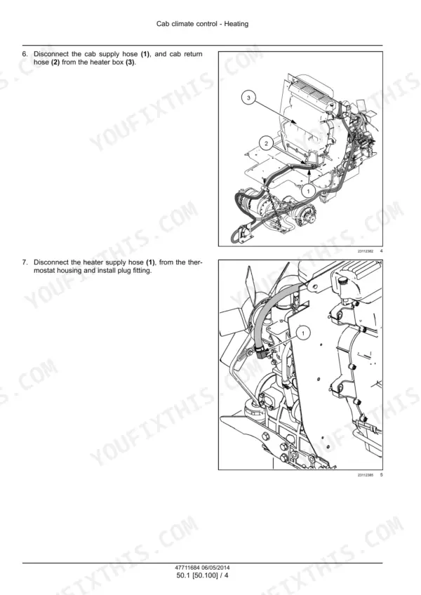
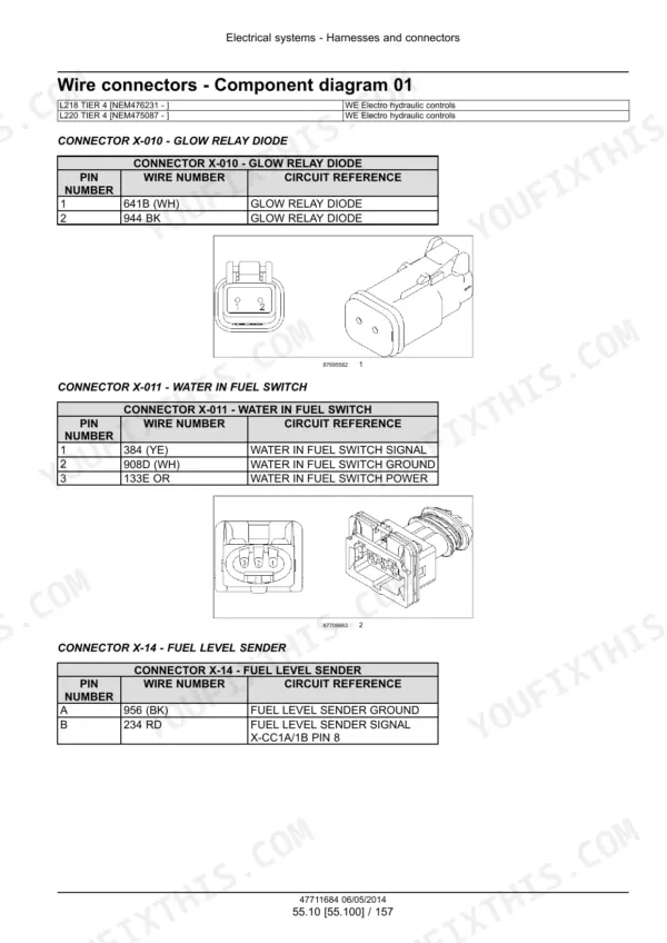
Part of the New Holland Repair Manuals.
This is New Holland service manual 47711684, 1st edition, May 2014.
It covers the L218 and L220 200 Series skid steers, Tier 4B (final): the L218 from PIN NEM476231 and above, and the L220 from PIN NEM475087 and above. It includes hydrostatic pump and drive motor tests, chain case and axle work, the loader valve, high flow, self-leveling and ride control. It also has wiring for mechanical and electro-hydraulic machines, plus UCM and engine fault codes.
The specifications give the charge, main and circuit relief pressures, pump flows and fill capacities to test against, and troubleshooting tables cover the hydrostatic pump and loader self-leveling.
What's Inside This New Holland L218, L220 Manual
| System | Pages | Key Topics |
|---|---|---|
| Introduction, Capacities and Torque Tables | 1-42 | PIN and Engine per Model, Contents, Safety Rules, Metric, Inch, Hydraulic and Pipe Thread Torque Tables, Basic Repair Instructions, Capacities |
| Engine Removal and Installation | 43-74 | Engine Oil Drain, Belt Installation and Tensioning |
| Front Axle and Chain Drive | 75-94 | Axle Removal, Disassembly, Assembly and Installation, Drive Chain Inspection and Measurement |
| Rear Axle and Chain Drive | 95-114 | Axle Removal, Installation, Disassembly and Assembly, Drive Chain Inspection and Measurement |
| Hydrostatic Transmission and Two-Speed Controls | 115-133 | Transmission Operation, Two-Speed Valve Specifications, Mechanical Control Adjustment |
| Hydrostatic Pump and Drive Motors | 134-244 | Pump and Motor Specifications, Charge and Main Relief Pressure Tests, Charge Pump and Valves, Pump Inspection, Disassembly and Assembly, Drive Motors |
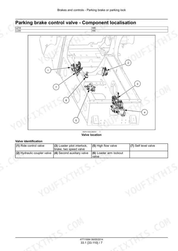
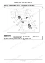
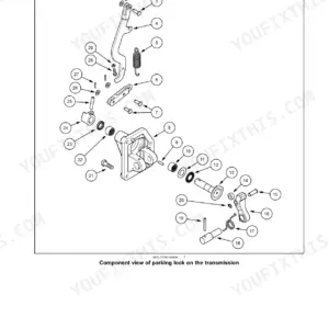
| Brakes | 245-256 | Parking Brake Control Valve, Valve Location, Electrohydraulic Pilot Pressure |
| Hydraulic Schematics and Service | 257-283 | Valve Locations, Hydraulic Schematics for Mechanical and Electro-Hydraulic Machines, Cleaning, Decontamination and Pressure Release |
| Gear Pump, Auxiliary Circuit, Reservoir and Filters | 284-323 | Gear Pump Specifications and Flow Test, Auxiliary Valve and Pressure Check, Reservoir, Oil Filters, Main Relief Valve |
| Main Control Valve and High Flow | 324-367 | Control Valve Specifications, Leakage Test, Spool Solenoids and Sensors, Removal and Installation, High Flow Valve and Pump Flow Test |
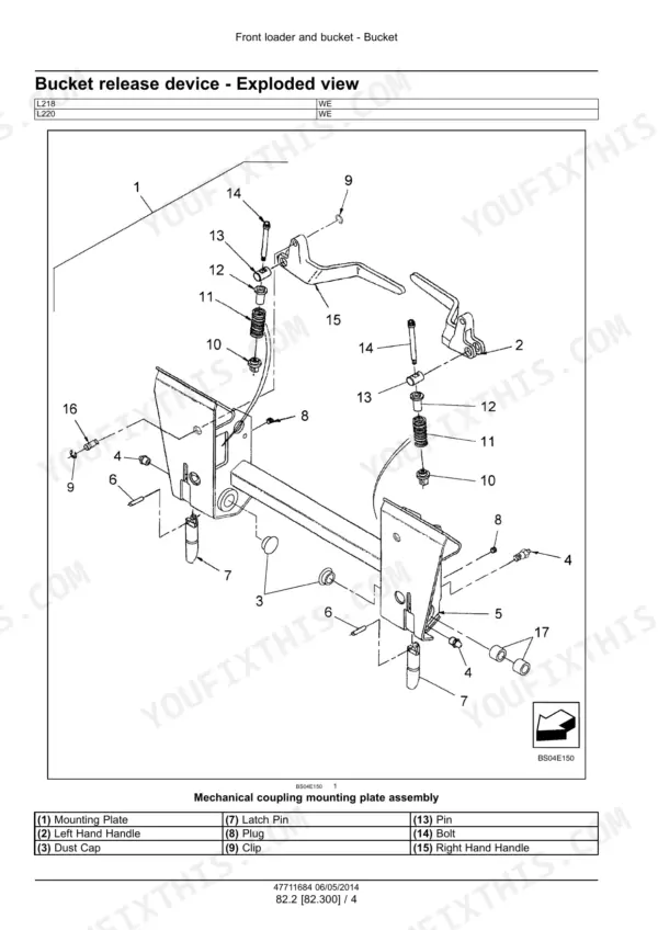
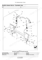
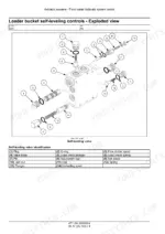
| Boom, Bucket, Self-Leveling and Coupler Hydraulics | 368-448 | Lock Valve, Ride Control and Accumulator Specifications, Boom Cylinders, Ride Control Valve, Accumulator, Bucket Cylinder, Self-Leveling, Coupler |
| Frame, Counterweight and Wheels | 449-470 | Counterweight Removal and Installation, Tire Pressure, Wheel Nut Torques |
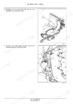
| Cab Climate Control | 471-508 | Heater Removal and Installation, Air Conditioning Specifications, Leak Test, Recovery and Charging |
| Electrical Overview, Calibration and Sensors | 509-575 | Electrical Overview, EST Calibration, Diode and Wire Checks, Fuel, Coolant and Air Sensors, Hydrostatic Sensors and Solenoids, Parking Brake |
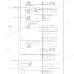
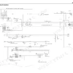
| Electrical Schematics, Mechanical Controls | 576-644 | Schematic Sheet Index, Fuse and Relay Box, Electrical Schematic Sheets 01 to 28 |
| Electrical Schematics, Electro-Hydraulic Controls | 645-721 | Main Power Distribution, Ignition and Charging, Engine ISM, Throttle Sensors, Hydraulic Interlocks, Loader Valve, Control Handles, Unit Control Module, Lamps, Wipers and Washers, Instrument Cluster, HVAC, Telematics, Diagnostic Connector |
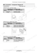
| Connector Diagrams | 722-899 | Connector Component Diagrams for Electro-Hydraulic and Mechanical Machines, ECU, Relays, Alternator, Switches, Fuse Board |
| Fuses, Relays and Harness Repair | 900-913 | Relay and Fuse Overview, Harness Repair and Replacement |
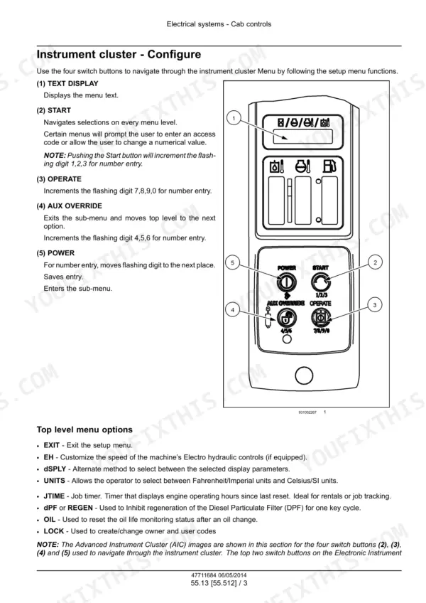
| Battery, Lights, Cab Controls and Modules | 914-963 | Battery, Work Lights, Instrument Panel Setup, Throttle, ECU Electrical Test |
| Fault Codes, UCM Controller (Part 1) | 964-1143 | Fault Code Index, Codes 1004 to 4754 for Hydraulic Filter, Oil Temperature, Throttle Sensors, Calibration, UCM Power, Parking Brake, Pump Valves, Swashplate Sensors |
| Fault Codes, UCM Controller (Part 2) | 1144-1369 | Codes 4781 to 9410 for Two-Speed Solenoid, Hydraulic Lockouts, Joysticks, Boom and Bucket Solenoids, EHF Pumps, Spool Sensors, Switches, Memory and CAN |
| Engine Fault Codes (ECU) | 1370-1516 | Engine Codes 1010 to 3977 for Reference Voltage, Temperatures, Boost Pressure, Crank and Cam Sensors, Injectors, EGR, Glow Plugs, Engine Speed, Code Index |
| Boom and Bucket | 1517-1550 | Boom Removal and Installation, Bucket Specifications, Coupler, Cutting Edge and Teeth |
| Cab Door and Special Tools | 1551-1559 | Cab Door Switch, Special Tool Index |
Quick Reference Specifications
| Specification | Value | Page |
|---|---|---|
| Fuel tank | 75.5 l (20.0 US gal) | p. 39 |
| Cooling system | 15.6 l (4.2 US gal) | p. 39 |
| Engine oil with filter change | 7 l (7.5 US qt) | p. 39 |
| Hydraulic reservoir | 15.0 l (3.96 US gal) | p. 39 |
| Hydraulic system total | 38.1 l (10.0 US gal) | p. 39 |
| Chain case, each side | 7.4 l (7.9 US qt) | p. 39 |
| Engine oil drain plug torque | 68 - 82 N·m (50 - 61 lb ft) | p. 46 |
| Gear pump flow at 2860 RPM | 73.1 L/min (19.3 US gpm) | p. 286 |
| Combined pump flow with high flow | 109.8 L/min (29.0 US gpm) | p. 286 |
| Main relief setting | 207 - 217 bar (3000 - 3145 psi) | p. 318 |
| Circuit relief settings | 220 - 235 bar (3190 - 3408 psi) A1 lift cylinder base; 255 - 270 bar (3698 - 3916 psi) A2 tilt cylinder rod; 225 - 240 bar (3263 - 3481 psi) B2 tilt cylinder base | p. 318 |
| High flow relief valve setting | 224 bar (3250 psi) | p. 350 |
| Hydrostatic charge pressure relief | 24 - 26 bar (350 - 370 psi) mechanical controls; 24 - 26 bar (347 - 377 psi) electro-hydraulic controls | p. 137 |
| Hydrostatic main relief | 345 - 362 bar (5000 - 5250 psi) mechanical controls; 350 - 370 bar (5075 - 5365 psi) electro-hydraulic controls | p. 137 |
| Charge pump flow | 27 l (7 US gal) minimum at 1800 RPM mechanical controls; 40 l (10.5 US gal) electro-hydraulic controls | p. 137 |
| Drive motor displacement | 325 cm³ (20 in³) | p. 139 |
| Drive motor brake release pressure | 11 - 15 bar (160 - 218 psi) | p. 139 |
| Wheel nut torque | 169.5 N·m (125 lb ft) taper nut; 203.5 N·m (150 lb ft) flange nut | p. 462 |
New Holland L218, L220 Common Problems This Manual Covers
One drive side works and the other does not
On an EH unit, run the EH pump electrical check and confirm calibration first. Then check power to the lock valve and brake valve, and confirm they work with the parking brakes released. Check the circuit relief pressure setting on the dead side. Finish with charge pressure and flow, using the tests in the Hydrostatic Pump and Drive Motors section.
Manual Section: Hydrostatic Pump and Drive Motors p. 239Machine does not have enough power
On an EH unit, start by checking calibration and electrics. If full throttle engine speed is OK but rated speed is low, the fault is in the engine or fuel system, so repair it there. If speeds are good, check charge pressure using the Hydrostatic Pump and Drive Motors section to find out whether the pump or the drive motors have failed.
Manual Section: Hydrostatic Pump and Drive Motors p. 239Loaded bucket dumps or uncurls with the control valve in neutral, or self-level falls short
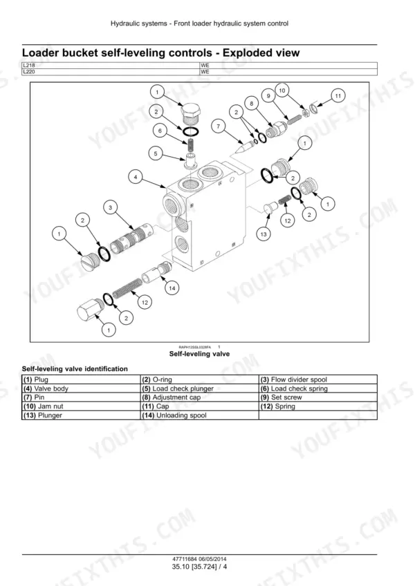
A bucket that uncurls under load with the valve in neutral points to a leaking unloading spool. Remove the spool and inspect it for damage. If self-level falls short, the adjustable orifice is out of adjustment and the self-leveling valve must be replaced. Both are covered in Boom, Bucket, Self-Leveling and Coupler Hydraulics.
Manual Section: Boom, Bucket, Self-Leveling and Coupler Hydraulics p. 430Fault code 1004, hydraulic filter restriction switch
Code 1004 means the hydraulic filter is restricted. Possible causes are a clogged filter, an open signal wire, a failed switch or a failed instrument cluster. Inspect the hydraulic filter and replace it if needed. Then check the harness and connectors, and measure the switch and signal wire. Resistance should be less than 10 Ω, per Fault Codes, UCM Controller.
Manual Section: Fault Codes, UCM Controller (Part 1) p. 972Frequently Asked Questions
Does this manual cover my New Holland L218 or L220 skid steer?
It covers the L218 from PIN NEM476231 and above and the L220 from PIN NEM475087 and above. These are the 200 Series Tier 4B (final) machines. It is New Holland service manual 47711684, 1st edition, English, May 2014. The engine is listed as N4LDI-TA-45SL on the L218 and N4LDI-TA-50SL on the L220. Check the PIN on your machine plate against those ranges before you order. p. 1
What are the New Holland L218 and L220 fluid capacities?
The fuel tank holds 75.5 l (20.0 US gal). The cooling system takes 15.6 l (4.2 US gal). Engine oil with a filter change is 7 l (7.5 US qt). The hydraulic system holds 38.1 l (10.0 US gal) in total, and 15.0 l (3.96 US gal) of that is in the reservoir. Each chain case takes 7.4 l (7.9 US qt), so fill both sides. p. 39
What are the New Holland L218 and L220 hydrostatic drive pressures?
Charge pressure relief is 24 - 26 bar (350 - 370 psi) on mechanical-control machines and 24 - 26 bar (347 - 377 psi) on electro-hydraulic machines. Hydrostatic main relief is 345 - 362 bar (5000 - 5250 psi) mechanical and 350 - 370 bar (5075 - 5365 psi) electro-hydraulic. Drive motor displacement is 325 cm³ (20 in³). Brake release pressure is 11 - 15 bar (160 - 218 psi). p. 137
What are the New Holland L218 and L220 loader hydraulic flow and relief settings?
The gear pump delivers 73.1 L/min (19.3 US gpm) at 2860 engine RPM. With the high flow pump fitted, combined flow is 109.8 L/min (29.0 US gpm). Main relief is 207 - 217 bar (3000 - 3145 psi), and the high flow relief valve is 224 bar (3250 psi). Circuit reliefs are A1 220 - 235 bar (3190 - 3408 psi), A2 255 - 270 bar (3698 - 3916 psi) and B2 225 - 240 bar (3263 - 3481 psi). p. 318
What is inside this manual: wiring diagrams, hydraulic schematics, fault codes?
It has electrical schematic sheets 01 to 28 for mechanical-control machines and 01 to 34 for electro-hydraulic machines, plus connector diagrams. Hydraulic schematics cover both control types. Each UCM and engine fault code lists context, cause, possible failure modes and a solution. There are troubleshooting tables for the hydrostatic pump and loader self-leveling. It does not include engine specifications or an engine overhaul. p. 964






Reviews
There are no reviews yet.