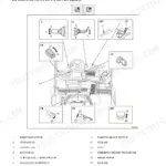
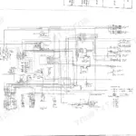
Mast unit disassembly, from the triplex mast with free lift to mast chains, guidance rollers and the free lift, side and initial lift cylinders, is laid out in full in this 320-page Mitsubishi 10N2 service manual PDF (OEM ID 616840) for eight N2 pedestrian stacker variants, 10N2 through 16N2S. Past the mast, wiring diagrams trace the power source, key switch, emergency stop safety circuit and AC traction motor, while hydraulic schematics with a symbol key map the hydraulic aggregate, down to setting the lifting pressure. Traction controller alarm codes, parameter descriptions, TruckTool diagnostics, accelerator calibration and an insulation resistance test round out the electrical side. Hold hydraulic fluid level at 50-70 mm. Traction motor power terminals take 6 Nm. When your fault sits among the traction controller connectors, contactors and fuses, the wiring schematic shows how each connection runs. Bought once, this bookmarked, text-searchable PDF stays yours to keep for your stacker.
What's Inside This Mitsubishi 10N2-16N2S Manual
| System | Pages | Key Topics |
|---|---|---|
| How to Read This Manual | 9-11 | Safety-Related Signs, Symbols and Abbreviations (Safety Symbols, Other Symbols and Abbreviations), Units |
| Safety Instructions | 12-15 | |
| General Information | 16-35 | Truck Model Covered by This Manual, Identification Plates on the Truck |
| Lifting Points | 36-38 | |
| Opening the Covers | 39-43 | |
| Traction Wheel | 44-56 | |
| Mast Unit | 57-164 | |
| Electrical Operation | 165-170 | Using the Schematic Diagram, Power Source, Safety Circuit, Key Switch, Traction, AC Motor Operation, Sensorless Operation |
| Battery Maintenance | 171-179 | Daily Maintenance, Weekly Maintenance, Monthly Maintenance, Annual Maintenance |
| Electric System Maintenance | 180-222 | Tiller Arm (Removing the Tiller Head, Removing the Tiller Head Switches, Removing the Safety Button, Removing the Accelerator, Installing the Accelerator, Removing the Controller for Lifting and Lowering, Installing the Controller for Lifting and Lowering) |
| Electric System Adjustments and Measurements | 223-228 | Calibrating the Accelerator (Acquiring VACC: with TruckTool, Without Truck Tool), Calibrating the Controller for Lifting and Lowering (Acquiring the VACC with TruckTool) |
| Hydraulic Operation | 229-237 | Hydraulic Symbols, Hydraulic Oil Recommendations, Maintenance Points of the Hydraulic System |
| TruckTool Diagnostics | 238 | Diagnostics Application, Data Bus, Controller Firmware, Alarm Management, Truck Setup |
| Parameter Descriptions | 239-246 | Traction Controller |
| Alarm Codes | 247-265 | Traction Controller |
| Service Data | 266-273 | Special Tightening Torques, Tightening Torque for Standard Bolts and Nuts, Maintenance Check List, Lubrication (Hydraulic Oil, Transmission Oil), Special Tools |
| Options | 274-300 | Load Support (Installation of the Load Support), Accessory Rack (Installation: List Bracket, Computer Rack, Bottle Rack, Pen Rack) |
| Technical Specification | 301-310 | Identification, Weights, Wheels, Tyres, Dimensions, Performance, Motors |
| Stickers | 315-320 | Type Plate, Mast Operation Warning Sticker, Serial Number Sticker, Battery Maintenance Warning Sticker, Electric Panel Cleanup Warning Sticker, Hoist Point Indication Sticker |
Quick Reference Specifications
| Specification | Value | Page |
|---|---|---|
| Traction motor power terminals tightening torque | 6 Nm | p. 31 |
| Hydraulic fluid level | 50-70 mm | p. 150 |
| Insulation resistance of the battery | 50 Ω per Volt of nominal voltage | p. 174 |
| Minimum insulation resistance for batteries up to 20 V nominal voltage | 1000 Ω | p. 174 |
| Handle installation time | 10 seconds | p. 186 |
| Face run-out of the motor's connecting face and the motor shaft | 0.04 mm | p. 206 |
| Pump motor contact rating | 24 Vdc / 1.2 kW | p. 211 |
| Voltage converter output | 12 V, 12.5 A | p. 282 |
| Transmission gear oil type | SAE 80W/90, API GL-5 | p. 43 |
| Total transmission oil quantity | 1.05 L | p. 43 |
| Wheel shaft bolt tightening torque | 27 Nm | p. 46 |
| Traction wheel nut tightening torque | 80 Nm | p. 47 |
Mitsubishi 10N2-16N2S Common Problems This Manual Covers
Mitsubishi 10N2 to 16N2S traction wheel worn down and truck no longer standing vertically straight
Measure the traction wheel diameter per page 44: at 220 mm adjust the castor wheel, at 214 mm replace the wheel. Support the lifted truck on safety blocks or rigid stands, never on jacks alone (pages 36 and 12). Replace damaged wheel shaft bolts with Loctite 243 at 27 Nm (page 46). Clean grease off the shaft and rim face, then torque the five cone nuts to 80 Nm on page 47.
Manual Section: Traction wheel maintenance p. 44Castor wheel bearing has excessive play or castor wheel does not rotate properly
Jack the truck up slightly to lighten the castor load, and support it on safety blocks or rigid stands (page 36). Measure the castor diameter: new is 98 mm, replace at 90 mm per page 47. After reassembly on page 49, check bearing play and free rotation, then adjust castor height within ±6 mm for vertical straightness (page 48).
Manual Section: Castor wheel maintenance p. 49Mast chain pairs show unequal tension, stretching, or loose fastenings during routine mast inspection
Lower the forks to the ground first, or block them so they cannot fall (page 12). Check that all chain fastenings are in order and that every chain pair carries equal tension, then check for stretching per page 69. Do not wash, sand blast, steam clean or paint the chains, and avoid oil or grease lubrication in dusty conditions (page 70).
Manual Section: Mast unit maintenance p. 69Pump motor running but display shows alarm 52, pump current 0A, PUMP I=0 EVER
Turn the key switch OFF, disconnect the battery plug and discharge the controllers before opening the motor compartment (page 204). Check the pump motor connection for continuity as page 251 directs; an open connection stops current flow and triggers this warning. Do not attempt to repair the pump motor itself (page 211). Do not pull the cables when checking connections.
Manual Section: Traction controller alarm codes p. 251Display shows warning 80 FORW+BACK with both travel direction demands active at the same time
Turn the key switch OFF and disconnect the battery plug before opening the tiller head (page 181). Use a tester on the direction switches as page 253 instructs to find why both travel demands read active. If a tiller head switch must come out, remove it carefully so you do not break it (page 183).
Manual Section: Traction controller alarm codes p. 253Traction motor temperature warning appears on the display even when the motor is cold
Turn the key switch OFF, disconnect the battery plug and discharge the controllers before opening the motor compartment (page 204). Measure the traction motor temperature sensor resistance against approximately 580 Ω on page 208. If the motor is cold and the sensor reads correctly, the fault is in the traction controller per page 252. Do not pull cables while checking connections.
Manual Section: Traction controller alarm codes p. 252Frequently Asked Questions
What are Mitsubishi 10N2, 12N2, 12N2I, 14N2, 14N2I, 16N2, 16N2I, 16N2S battery and battery connector replacement specs?
When replacing the battery, use one with similar dimensions and weight to maintain the stability and braking properties of the truck. The battery's minimum weight is indicated on the identification plate of the truck. Ensure the mechanical voltage selector is set to 24 V and note the polarity of the battery cables. p. 177
What is the correct tightening torque for the traction controller power terminal bolts on the Mitsubishi 10N2-16N2S?
The correct tightening torque for the traction controller power terminal bolts is 7 Nm (±1.4 Nm). p. 198
What is the procedure for bleeding air from the free lift cylinder?
After replacing seals, lift the forks to their upmost position, then lift the mast unit so the lifting carriage is raised by one meter. Loosen the air bleeding screw (part 8 on page 145) and let air bleed out until only hydraulic fluid flows. Tighten the screw and repeat as necessary, then fill the hydraulic tank to 50-70 mm from the bottom. p. 151
What is the mast chain inspection interval on the Mitsubishi 10N2, 12N2, 12N2I, 14N2, 14N2I, 16N2, 16N2I, 16N2S?
Mast chains should be inspected and lubricated after each 300 hours of operation, or more frequently if the truck is used in severe or extreme environments. p. 131
What is the standard thickness of the fork blade and when should it be replaced?
The standard thickness of the fork blade is 40 mm. You should replace the forks when the thickness of the fork blade reaches 31 mm. p. 124
Is this Mitsubishi 10N2 manual a download or a disc?
You get a 320-page searchable PDF that downloads instantly after checkout. Open it on your laptop, tablet, or phone, and bring it right to the shop floor.
Can I print specific sections of this Mitsubishi 10N2 Service Manual?
Yes. Print the sections you need to take out to the shop for your own use. Standard letter or A4 paper works.