
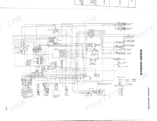
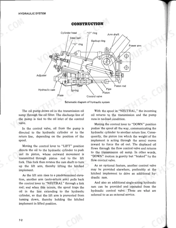
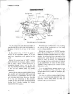
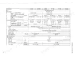
Getting a clutch split, head job or lift pump overhaul right the first time is what the 348 pages of factory manual 83-2-300 are for, covering six variants of Mitsubishi's MT160 and MT180 tractor series, hydrostatic H models included. Wiring diagrams in this Mitsubishi MT160 repair manual PDF trace your circuits from the battery and starter switch through the alternator, regulator and glow plugs, while hydraulic schematics follow oil from the pump through the control valve and lift lock valve. Hydraulics take up nearly a fifth of the book, and the hydrostatic transmission gets its own chapter, down to the charge pump, neutral valve and differential lock. Set injection nozzles at 120 kg/cm² (1706 psi), and replace the clutch disc once the rivet heads sit within 0.3 mm (0.012 in.) of the facing. Every dry day the tractor sits idle costs fieldwork. Bookmarked, text-searchable pages take you straight to the chapter, and the machine is pulling its tiller again.
What's Inside This Mitsubishi MT160, MT180 Series Repair Manual
| System | Pages | Key Topics |
|---|---|---|
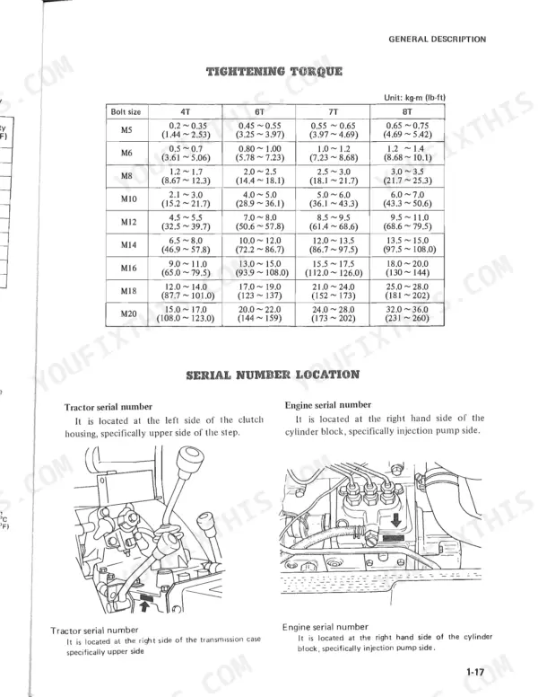
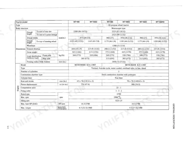
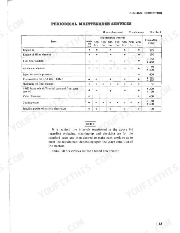
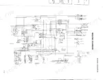
| General Description | 5-26 | Specifications, Greasing Diagram, Periodical Maintenance Services, Lubrication Table, Wiring Diagram, Tightening Torque |
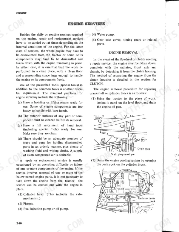
| Engine System | 27-98 | Cylinder Head Assembly, Cylinder Block Assembly, Lubrication System, Fuel System, Governor System, Cooling System |
| Clutch System | 99-120 | Clutch Release Mechanism, Clutch Cover Assembly, Clutch Disc, Clutch Shifter, Clutch Pedal |
| Front Axle and Steering Linkage System | 121-148 | 4-Wheel Drive, Steering Gearbox, 2-Wheel Drive, Front Wheel Hubs, Kingpins |
| Transmission System Sliding Gear Type | 149-176 | Transmission Gears, Shafts, Shift Mechanisms, Differential Gearing, Spiral Bevel Gear Drive, Differential Lock |
| Transmission System Hydrostatic Transmission | 177-213 | Charge Pump, Low Pressure Relief Valve, Neutral Valve, Main Transmission, PTO Gear, Differential Lock |
| Brake System | 214-227 | Brake Cover, Brake Drum, Brake Shoe, Brake Cam, Brake Pedal, Parking Brake |
| Hydraulic System | 228-293 | Hydraulic Case, Control Valve, Hydraulic Pump, Lift Lock Valve, Oil Filter, Suction Pipe |
| Electrical System | 294-327 | Battery, Safety Starter Switch, Starter, Alternator, Regulator, Glow Plugs |
| Others | 328-348 | Rotary Tiller, Front Power Take-Off Kit |
Quick Reference Specifications
| Specification | Value | Page |
|---|---|---|
| Max. torque | 4.5 kg-m (32.5 ft-lb) at 1900 rpm | p. 2 |
| Clutch disc diameter | 184 x 127 mm (7-5/16 x 5-1/32 in.) | p. 5 |
| Clutch disc rivet head to facing service limit | 0.3 mm (0.012 in.) | p. 113 |
| Water pump feeding capacity | 52 l/min (13.7 U.S. gal/min) at 2600 engine rpm | p. 3 |
| Oil filter tightening torque | 1.1 to 1.3 kg-cm (0.08 to 0.09 lb-ft) | p. 61 |
| Fuel injection nozzles injection pressure | 120 +10/-0 kg/cm² (1706 +142/-0 psi) | p. 4 |
| Hydraulic pump output | 12.9 liter/min. (3.4 GPM) | p. 253 |
| Lining dimension (length x width x thickness) | 119 x 28.5 x 4.0 mm (4.7 x 1.12 x 0.16 in.) | p. 15 |
| Antifreeze Freezing point -45.2°C (-49.4°F) | 55% concentration | p. 24 |
| Relief pressure | 135 +5 kg/cm² (1920 +71 0 psi) | p. 289 |
| M5 Bolt Torque (4T) | 0.2 ~ 0.35 kg-m (1.44 ~ 2.53 lb-ft) | p. 25 |
| Thermostat valve opening temperature | 82°C (180°F) | p. 77 |
Mitsubishi MT160, MT180 Series Common Problems This Manual Covers
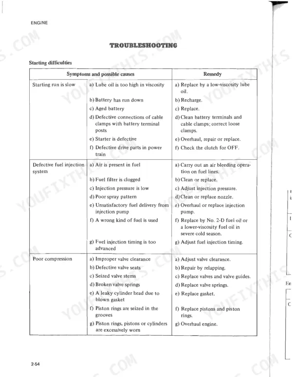
Mitsubishi MT160 and MT180 tractor diesel engine cranks with a slow starting run and is hard to start
Check the glow plugs first, then work through the slow cranking, fuel injection, compression and governor causes. Test each nozzle for an injection starting pressure of 120 +10/-0 kg/cm² (1,706.97 +142.25/-0 psi) per page 93. Torque the glow plugs to 1.5 to 2 kg-m (10.8 to 14.5 ft.lbs.) when you reinstall them.
Manual Section: Engine Starting DifficultiesTractor engine not making enough output power, running rough, burning oil, or making abnormal noises
Check which symptom you have on pages 85 and 86 (low output power, high oil consumption, abnormal noise or rough running) and work through the causes listed for it in order. If the diagnosis takes you into the cylinder head, torque the M12 head bolts to 11 to 12 kg-m (79.5 to 86.8 ft.lbs.) and the M10 bolts to 7 to 8 kg-m (50.6 to 57.8 ft.lbs.) per page 96.
Manual Section: Engine Output PowerClutch slips under load, engine revs climb while the tractor loses pulling power
Check clutch pedal free play first and set it to 20 ~ 30 mm (0.79 ~ 1.18 in.) per page 116. If it still slips, pull the disc and inspect it for oil or grease on the facings, worn facings and corroded splines. Replace any disc that wobbles 1 mm (0.03 in.) or more.
Manual Section: Clutch Slippage p. 118Clutch shudders on engagement and overheats when starting off from a standstill
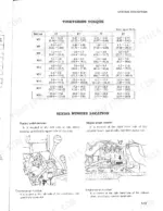
Remove the clutch and inspect it for a hardened disc surface, rust in the spline, weakened torsion springs and a burnt release bearing, working through the chart on page 118. Replace the worn parts, then torque the clutch cover to flywheel bolts to 2.5 ~ 3.0 kg-m (18 ~ 22 ft-lb) per page 113 before you head back to the field.
Manual Section: Clutch Shuddering and Overheating p. 118Hydrostatic transmission tractor will not move, will not gain speed, or stops under slight load
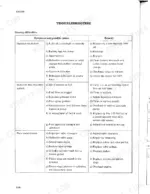
Check the charge pump, low pressure relief valve and neutral valve first when the tractor will not move, will not gain speed or stops under slight load. Then work through the hydrostatic transmission troubleshooting chart by symptom, including travel in only one direction, vibration and rising oil temperature, before you split the main transmission.
Manual Section: Transmission System Hydrostatic Transmission p. 177Three-point hitch implement will not lift, raises slowly, or lowers with the lever in neutral
Clean the hydraulic oil filter and inspect the suction pipe, then test relief pressure against 135 +5/-0 kg/cm² (1920 +71/-0 psi) using the chart on page 289. If the implement lowers in neutral or will not lower, inspect the control valve and lift lock valve before you condemn the hydraulic pump.
Manual Section: Hydraulic System Troubleshooting p. 289Frequently Asked Questions
What are the torque specifications for the cylinder head bolts on the Mitsubishi MT160 and MT180?
The cylinder head bolts for the M12 screws should be tightened to 11 to 12 kg-m (79.5 to 86.8 ft-lbs), and the M10 screws should be tightened to 7 to 8 kg-m (50.6 to 57.8 ft-lbs). p. 96
What are the replacement specifications for the clutch disc on the Mitsubishi MT160, MT180?
The clutch disc should be replaced if the recession of the rivet heads from the facing is less than 0.3 mm (0.012 in.). When installing a new disc, ensure the recession is between 1.2 and 2.0 mm (0.05 to 0.08 in.). p. 113
What is the valve clearance specification for the engine on the Mitsubishi MT160, MT180?
The valve clearance for both intake and exhaust valves should be 0.25 mm (0.01 in.) when the engine is cold. p. 10
What is the correct engine oil capacity for the MT160 and MT180?
The engine oil capacity is 3 liters (6 pints) for the oil pan. p. 19
What is the specified injection pressure for the fuel injection nozzles on the Mitsubishi MT160, MT180?
The injection pressure for the fuel injection nozzles is 120 +10/-0 kg/cm² (1706 +142/-0 psi). p. 11
Will this Mitsubishi MT160 Repair Manual download right away?
A single searchable PDF file of 348 pages, downloadable right after payment. Nothing ships, nothing waits in the mail.
Can I print this Mitsubishi MT160 manual?
Yes. The PDF has no DRM restrictions, so print any page or section you need for your shop. Works with any standard printer.


Reviews
There are no reviews yet.