
Part of the New Holland Repair Manuals.
The complete New Holland factory repair manual for the HW305, HW305S and HW325 self-propelled windrowers, part number 87576230, bound as separately numbered books 87576231 through 87576237.
Sections run from general information through engine overhaul, front mechanical drive, the hydrostatic ground drive, brakes, hydraulic systems, rear axle, climate control, a large electrical section with SPN/FMI fault codes and full wiring harness diagrams, header attachments, optional equipment and the cab.
The torque tables are machine specific, and the manual keeps HW305/HW305S and HW325 separate throughout, right down to which hydraulic manifold components each model actually carries. This is the book the dealer techs worked from, not a generic reprint.
What's Inside This New Holland HW305 to HW325 Repair Manual
| System | Pages | Key Topics |
|---|---|---|
| Table of Contents | 1-64 | Repair Manual, Complete Contents, Book 1 - 87576231, General Information, Engine, Engine (Continued), Fuel System |
| General Information (Section 00) | 65-86 | General Information, Precautionary, Statements, Personal Safety, Precautionary Statements, General Safety Information, Service Machines Safely |
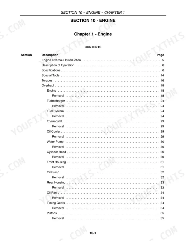
| Engine (Section 10) | 87-276 | Engine, Description, Engine Overhaul Introduction, Description of Operation, The Power Supply Is a Four Stroke Turbo Charged, Cylinder Unit and Crankshaft Components, Cylinder Head -- Timing System |
| Front Mechanical Drive (Section 25) | 277-300 | Front Mechanical Drive, Description of Operation, Using a Suitable Jack, Raise the Windrower, Installation, Planetary Gearbox Drive, Disassembly, Assembly |
| Hydrostatic Transmission (Section 29) | 301-446 | Ground Drive, Description, Specifications, Hydrostatic System, Hydrostatic Transmission, Identification, Each Pump and Motor Will Have a Nameplate |
| Brakes and Controls (Section 33) | 447-464 | Brakes and Controls, Description of Operation, Installation, Rotating, Stationary, And Primary, Disc Assembly, Brake Bleeding Procedure, Labor Guide |
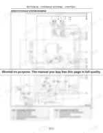
| Hydraulic Systems (Section 35) | 465-636 | Hydraulic Systems, Description, Introduction, System Component Locations, Reading Diagram Symbols, Flow Divider, Hydraulic Diagrams Are Made Up of a Group of |
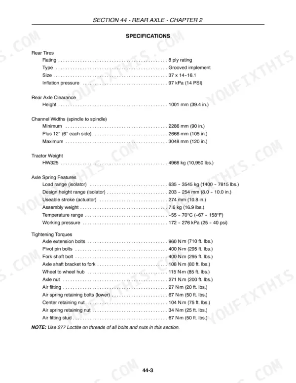
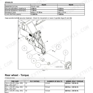
| Rear Axle (Section 44) | 637-686 | Non-Suspended Rear Axle, Introduction, Specifications, Rear Tires, Description of Operation, Extensions and Axle Tube, Adjustments |
| Climate Control (Section 50) | 687-836 | Climate Control -- Hw305 and Hw305S, Description, Specifications, Compressor, Description of Operation, The Basics of Refrigeration, High Side |
| Electrical - Chapters 1 to 4 | 837-1046 | General Information, Description, Introduction, Fault Codes and Fault Finding, In Circumstances Where Fault Finding Procedures, Electrical Terms and Equipment, Definitions |
| Electrical - Chapters 5 to 10 | 1047-1163 | Engine Electrical Systems, General Information, Air Filter Restriction Switch, Troubleshooting, Fuel Level Sender Circuit, Coolant Temperature Circuit, The Coolant Temperature Sensor (R--03), 1, Is |
| Electrical - Chapter 11 | 1164-1377 | Fault Codes, Description, Introduction, Fault Code Format (Spn/Fmi Codes), Spn Codes, Engine System, System ID |
| Electrical - Chapters 12 to 15 | 1378-1604 | Standard Wiring Harness Diagrams, Standard Wiring Harnesses, Fm Harness (Front), Cm Harness (RH Console), Ca Harness (Roof), Standard Wiring Harnesses (Hw325), Wiring Harnesses |
| Electrical - Chapters 15 Onward | 1605-1744 | Description, A-Pillar Display, Wire Harness Routing/Connections, Troubleshooting, Automatic Temperature Control, Wire Harness Routing, Radio Power and Ground Supply Test |
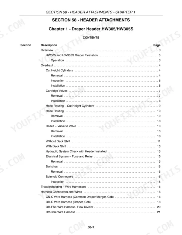
| Header Attachments (Section 58) | 1745-1846 | Draper Header Hw305/Hw305S, Description, Cartridge Valves, Removal, Installation, Hose Routing, Hoses -- Valve to Valve |
| Optional Equipment (Section 88) | 1847-1928 | Optional Equipment -- Hw305/Hw305S, Description, Optional Kits, Installation, Adjustable Windrow Shield, Cold Start Kit, Auxiliary Fuel Tank |
| Platform, Cab and Decals (Section 90) | 1929-2030 | Hw305 and Hw305S, Introduction, Removal, Installation, Cab Door Handle, Disassembly, Reassembly |
Quick Reference Specifications
| Specification | Value | Page |
|---|---|---|
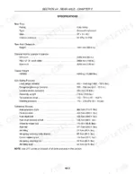
| Reservoir Capacity (All) | 60.5 liters (16 gallons) | p. 305 |
| Hydrostatic Pump Displacement (All) | 44 cc/REV max. | p. 305 |
| Hydrostatic Pump Relief Setting (system warm) (All) | 383.3 bar (5560 PSI) | p. 305 |
| Charge Pump Displacement (All) | 16.4 cc/REV (15.5 GPM) | p. 305 |
| Charge Pump Relief Setting (All) | 20 bar (290 PSI) | p. 305 |
| Hydrostatic Motor Displacement (High Speed) (HW325) | 46 cc/REV or 2.8 cu. in./REV | p. 305 |
| Hydrostatic Motor Displacement (Low Speed) (HW325) | 35 cc/REV or 2.1 cu. in./REV | p. 305 |
| Hydrostatic Motor Displacement (HW305/305S) | 44 cc/REV or 2.65 cu. in./REV | p. 305 |
| Motor Loop Flush For Cooling (All) | 9.4 - 11.4 L/min. (2.5 - 3 gpm) | p. 305 |
| Motor Charge Relief Valve Setting (All) | 14.4 - 15.2 bar (210 - 220 PSI) | p. 305 |
| Charge Pressure (low side of hydro motor, hydro stroked) (All) | 20 bar (290 PSI) | p. 305 |
| Case Pressure (Continuous) (All) | 1.7 bar (25 PSI) max. | p. 305 |
| Case Pressure (Cold Start) (All) | 5.2 bar (75 PSI) max. | p. 305 |
| Case Pressure (Relief In Motor) (All) | 14.4 bar (210 PSI) | p. 305 |
| Case Pressure (hydro in neutral, parking brake on, engine full throttle) (All) | 1.7 bar (25 PSI) | p. 305 |
| Case Pressure (hydro stroked, parking brake on, engine full throttle) (All) | 2.0 bar (30 PSI) | p. 305 |
| Case Drain Flow (Motors) (All) | 3.0-3.5 GPM max | p. 305 |
| Ground Drive pump type (All HW5 series windrowers) | Tandem variable-displacement piston pump | p. 480 |
| Charge pump type (All HW5 series windrowers) | Fixed-displacement | p. 311 |
| Transmission type (HW305/305S) | Hydrostatic | p. 301 |
New Holland HW305 to HW325 Common Problems This Manual Covers
Draper, knife or header drive slows down and stalls in heavy crop without much apparent load
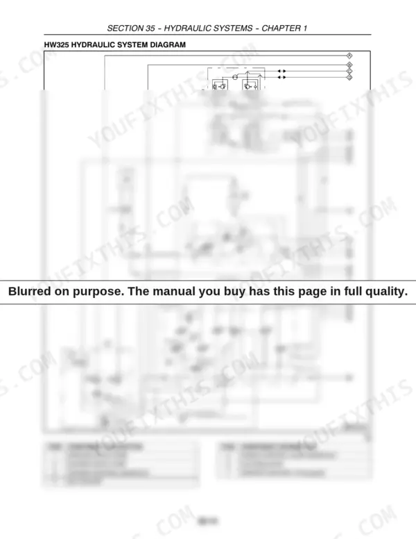
Start with Hydraulic Systems (Section 35): it locates every system component, teaches the diagram symbols, and includes the full HW325 hydraulic diagram naming the header drive pump, manifolds and oil cooler, so you can flowmeter-test drive relief pressure and isolate a leaking header drive motor instead of condemning the pump.
Manual Section: Hydraulic Systems (Section 35) p. 478Loss of propulsion or a hydrostatic drive that feels weak and will not pull
Section 29, Ground Drive, identifies each pump and motor by nameplate and gives the hydrostatic system specifications you test against. Check charge pressure and the relief valves first; the section carries the relief valve and mounting torques so a teardown goes back together to spec, not by feel.
Manual Section: Hydrostatic Transmission (Section 29) p. 307Machine will not start because propulsion or steering is not seen as neutral
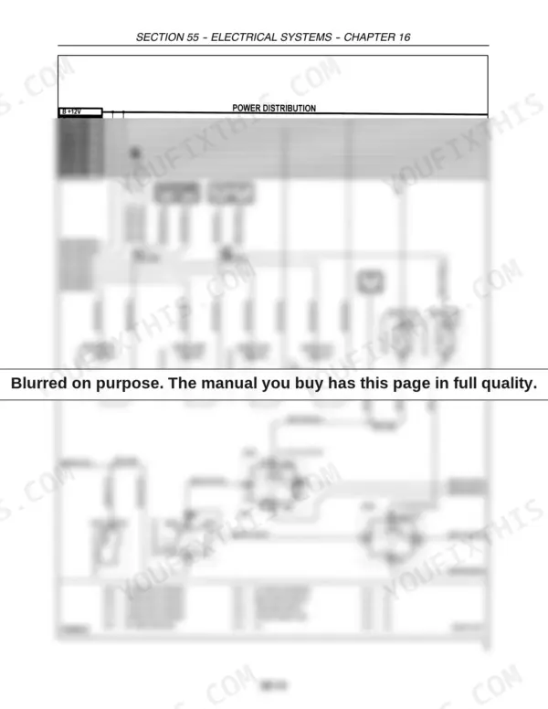
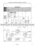
Work the fault finding procedures in the Electrical section, Chapters 1 to 4, then follow the sensor circuit through the standard wiring harness diagrams in Chapters 12 to 15. The manual separates a propulsion sensor that has drifted out of calibration from a wiring or connector fault, which are the two usual culprits.
Manual Section: Electrical - Chapters 1 to 4 p. 1690Hydrostatic system runs hot or noisy, sometimes with a high temperature fault on the display
Section 29 covers the internal causes: low oil, cavitation from a restricted suction path, and worn rotating groups. Then use the hydraulic diagram in Section 35 to trace the oil cooler circuit for restriction, and Chapter 11's SPN/FMI fault code list to read what the machine is reporting.
Manual Section: Hydrostatic Transmission (Section 29) p. 637Frequently Asked Questions
What do New Holland HW305 and HW325 error codes mean, and does this manual decode them?
Yes. The electrical section has a dedicated fault codes chapter that explains the SPN/FMI code format, lists engine system SPN codes by system ID, and walks you through fault finding when a code alone does not tell the whole story. That matters on these machines because a lot of no-go conditions show up first as a code on the display. p. 478
My windrower will not start until I wiggle the steering or propulsion control. Is that covered?
That is the classic propulsion sensor neutral mismatch, and it is an electrical troubleshooting job, not a starter problem. The electrical chapters cover the fault finding procedure, sensor circuits and wiring harness diagrams you need to check whether the sensor is out of its calibrated neutral range, the wiring is at fault, or the sensor itself has died. p. 1690
Does it cover the hydrostatic drive when the machine feels weak or loses propulsion?
Section 29 is the ground drive section. It identifies each pump and motor by its nameplate, gives specifications for the hydrostatic system, and covers removal, repair and installation. Weak drive usually comes down to charge pressure, a worn pump or contaminated oil, and this section gives you the specs to test against instead of guessing and swapping parts. p. 307
Are real torque specs included, or just generic values?
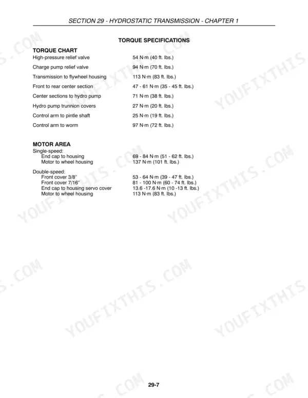
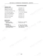
Real ones. For example, the hydrostatic section specifies 54 N.m (40 ft. lbs.) on the high-pressure relief valve, 94 N.m (70 ft. lbs.) on the charge pump relief valve, 113 N.m (83 ft. lbs.) transmission to flywheel housing, and 137 N.m (101 ft. lbs.) motor to wheel housing. Every mechanical section carries its own figures like these. p. 513
Is the HW325 actually covered, or is this an HW305 manual with the big machine as a footnote?
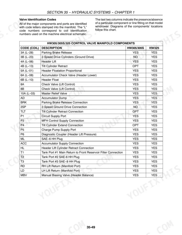
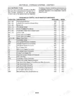
All three models are covered as distinct machines. The control valve manifold section includes a per-model table showing every manifold code and port and whether it exists on the HW305/HW305S versus the HW325, and the electrical section carries separate HW325 wiring harness diagrams. Several hydraulic components sit on one model and not the other, and the manual says which. p. 65







Reviews
There are no reviews yet.