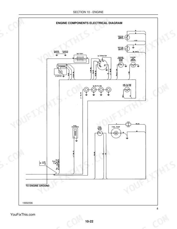
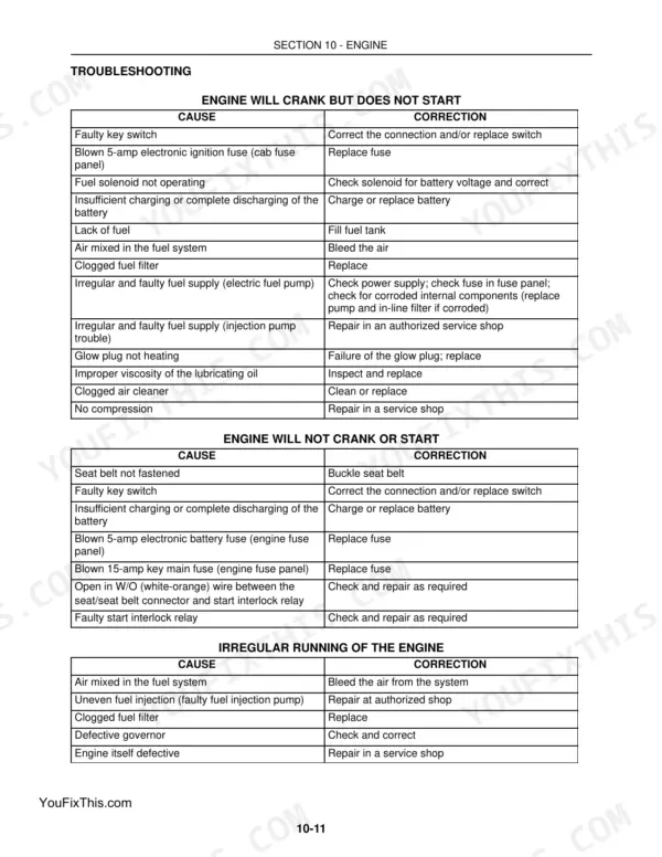
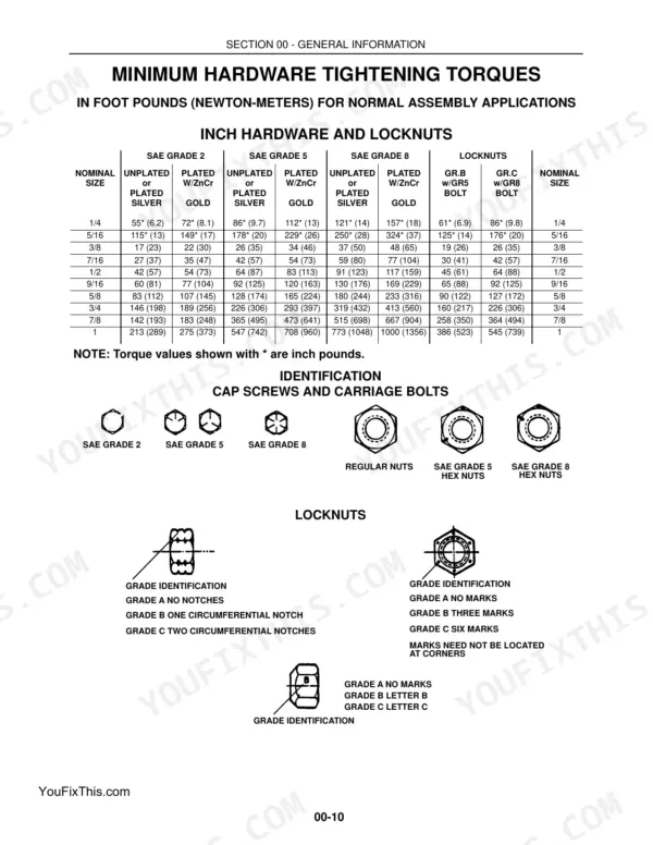
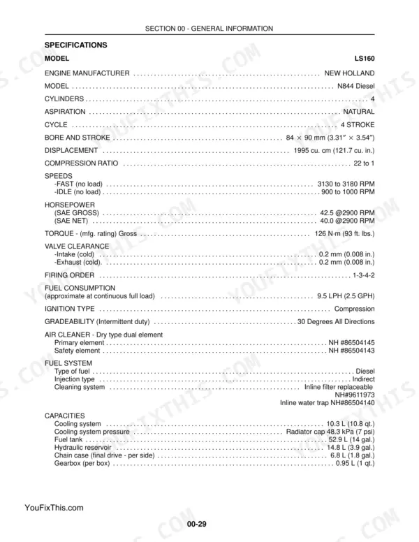
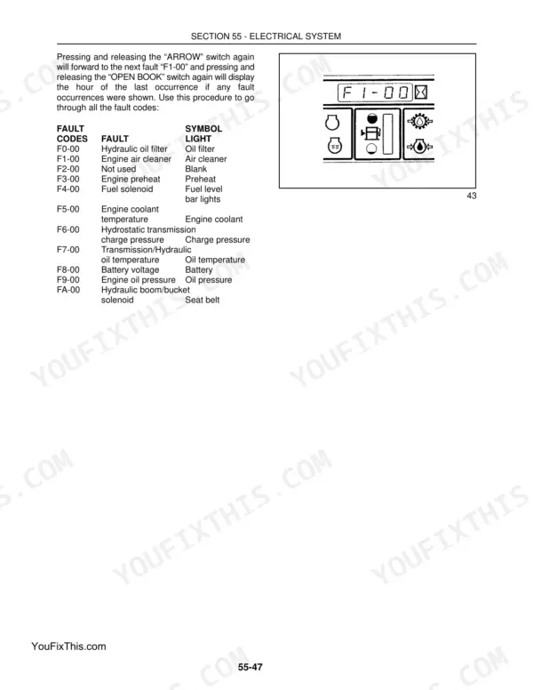


This 741-page New Holland LS160, LS170 Service Manual gets into the N844 Diesel engine and every system on your skid steer, from hydrostatic transmission to the front loader boom. Inside: wiring diagrams for the full electrical system, hydraulic schematics covering the 322-479 page range, and a troubleshooting section built around real DTC codes, not vague symptoms. You get torque specs, fluid capacities, and maintenance intervals laid out the way New Holland techs actually use them on the shop floor. Set your main system relief at 170-177 bar (2500-2600 PSI) on the LS160, and check injector setting between 2132-2277 PSI before you chase a stalling complaint elsewhere. No more guessing at pressure specs while your hydraulics sit dead. This PDF is bookmarked by section, so you jump straight from cover to Cab Climate Control, Electrical, or the Front Loader chapter without scrolling through 700 pages first.
Complete the set for your LS160, LS170, N844 Diesel
- Parts Catalog: New Holland LS170, LS160, SL55 Parts Catalog
- Parts Catalog: New Holland LS160, LS160E, SL45 Parts Catalog
What's Inside This New Holland LS160, LS170, N844 Diesel Manual
| System | Pages | Key Topics |
|---|---|---|
| General Information | 1-36 | Adjustable Fittings, Hydraulic Tubes, Pipe Thread Fitting, Locknuts, Cap Screws, Carriage Bolts, Hex Nuts, Skid Steer Cab |
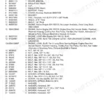
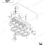
| Engine | 37-160 | Cylinder Head, Piston, Piston Ring, Connecting Rod, Crankshaft, Camshaft, Valve, Pushrod |
| Rear Drive Axle (Gearboxes) | 161-180 | Gearboxes, Final Drive System, Chain Case, Parking Brake |
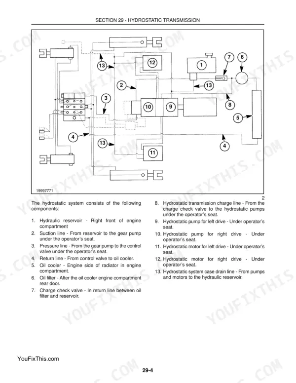
| Hydrostatic Transmission | 181-299 | Neutralizer, Pumps, Motors, Hydrostatic Drive System, Hydrostatic Pumps, Hydrostatic Motors, Charge Pressure System, Steering System |
| Brakes and Controls | 300-321 | Parking Brake, Chain Case, Brake Caliper, Brake Control Linkage, Spring Brake Assembly, Brake Caliper and Disc |
| Hydraulic System | 322-433 | Valves, Gear Pump, Cylinders, Pedal Controls, Control Valve, Hydraulic Pump, Boom Cylinders, Bucket Cylinders |
| Frames | 434-445 | ROPS, ROPS Frame, Labor Guide |
| Axles and Wheels | 446-469 | Axles, Wheels, Axle Housing Assembly, Final Drive, Drive Chain, Sprocket, Tires |
| Cab Climate Control | 470-477 | Switch and Control Panel, Relay and Fuse Block, Heater Core, Heater Shutoff Valve, Heater Fan Assembly, Filter |
| Electrical System | 478-637 | Electronic Instrument Cluster (Eic), Battery, Ignition Switch, Cab Fuse Panel, Alternator, Starter |
| Front Loader (Boom and Mounting Plate) | 638-679 | Buckets, Boom Lock Pins and Linkage, Attachment Mounting Plate, Boom and Cylinder Pivot Pins, Pallet Fork, Utility Fork |
| Accessories | 680-715 | Adapting Attachments, Back-Up Alarm, Block Heater (Engine), High Flow Hydraulics, Horn, Warning Light |
| Platform, Cab, Bodywork, and Decals | 716-741 | Seat and Seat Pan Support, Cab Inner Shell, Seat Removal, Seat, Switch and Pan Reinstallation, Safety Decals |
Quick Reference Specifications
| Specification | Value | Page |
|---|---|---|
| Main system relief | 170 - 177 bar (2500 - 2600 PSI) | p. 30 |
| Injector Setting Pounds per sq. inch (PSI) | 2132-2277 | p. 43 |
| For injection pump | 1.6512"-1.6559" (41.94-42.06) | p. 55 |
| V-belt (fan) slack - 0.2" (5 kg) at center | 0.2" (5 kg) | p. 56 |
| Oil relief valve | 44-51 ft. lbs. (60-69 N·m) | p. 57 |
| Pump Mounting Hardware | 39 N·m (29 ft. lbs.) | p. 330 |
| Pump Body Hardware | 35 N·m (26 ft. lbs.) | p. 330 |
| Relief Valve | 170 - 177 bar (2500 - 2600 PSI) Nonadjustable | p. 329 |
| Bushings | Teflon coated | p. 375 |