
![New Holland E115SR E135SR Repair Manual [Crawler Excavator]](https://youfixthis.com/wp-content/uploads/2012/02/Manual_Download-300x300.jpg)
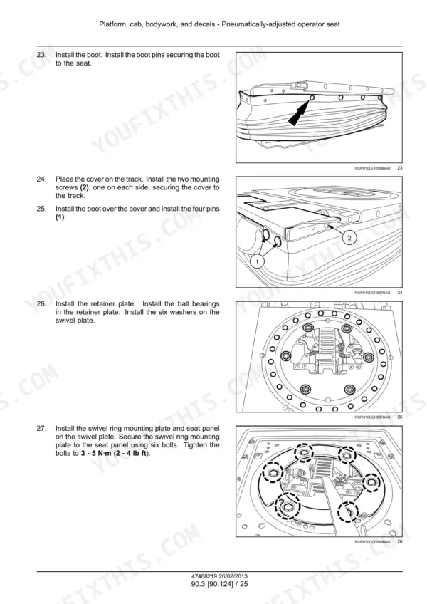
The New Holland service manual for the T9.390, T9.450, T9.505, T9.560, T9.615 and T9.670 articulated tractors, publication 47488219, dated 26/02/2013, 4015 pages. The serial applicability printed on the sheets is [ZCF200001 - ] WE and [ZDF200001 - ] WE, the Tier 4 machines with SCR and DEF/AdBlue. Two parts of the book were rendered and checked.
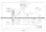
Page 1902 carries the composite hydraulic schema, a full colour circuit for the whole tractor. Its colour key separates PFC piston pump supply high pressure and regulated, charge pump flow, return to tank, Megaflow PFC piston pump supply, axle lube supply and fan drive pump supply, and pages 1900 and 1901 carry its 54-item numbered key.
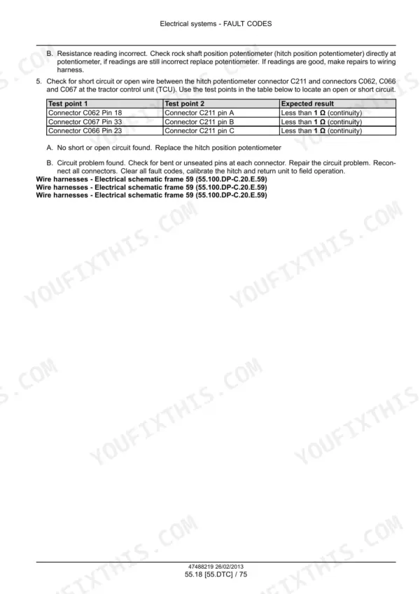
The colour electrical schematic frames start at page 2456 with frame 01, FUSE 1 TO 14, drawn to cab fuse/relay module 1. Every fuse on it is named with its rating, among them hazard/turn flasher 25.0 A, ignition circuit 15.0 A, ICU controller 10.0 A, TCU controller-main 10.0 A, colour display 10.0 A, horn 15.0 A and engine-ECM controller 20.0 A. Wire codes carry gauge and colour, and arrows cross-reference the sheet each circuit continues on. Know this before you buy: pages 2876 to 3833, just under a quarter of the book, are the fault code (DTC) reference, one entry per code with its test steps and connector checks. On a Tier 4 tractor, that is where most repairs start.
Complete the set for your T9 Series
- Operator Manual: New Holland T9.390–T9.670 Tractor Operator Manual
What's Inside This New Holland T9 Series Manual
| System | Pages | Key Topics |
|---|---|---|
| Introduction & Contents | 1-41 | How the Manual Is Organised, Section and Subsection Numbering, Safety Notices |
| Engine | 42-233 | Air Cleaners and Lines - 202, Engine Cooling System - 400, Fan and Drive - 414, Selective Catalytic Reduction (SCR) Exhaust Treatment - 500 |
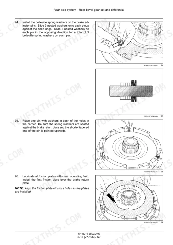
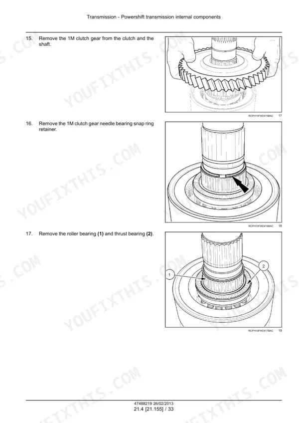
| Transmission - Powershift Overhaul | 234-415 | Removal and Installation, Clutch Packs and Shafts, Bearing Settings |
| Transmission - External Controls & Gearbox Internals | 416-487 | Powershift Transmission External Controls - 135, Gearbox Internal Components - 145 |
| Transmission - Powershift Internal Components - 155 | 488-795 | Clutch and Brake Assemblies, Shaft and Gear Inspection Limits, Reassembly Clearances |
| Front Axle System - Housing & Carrier | 796-849 | Front Axle Removal and Installation, Housing Inspection |
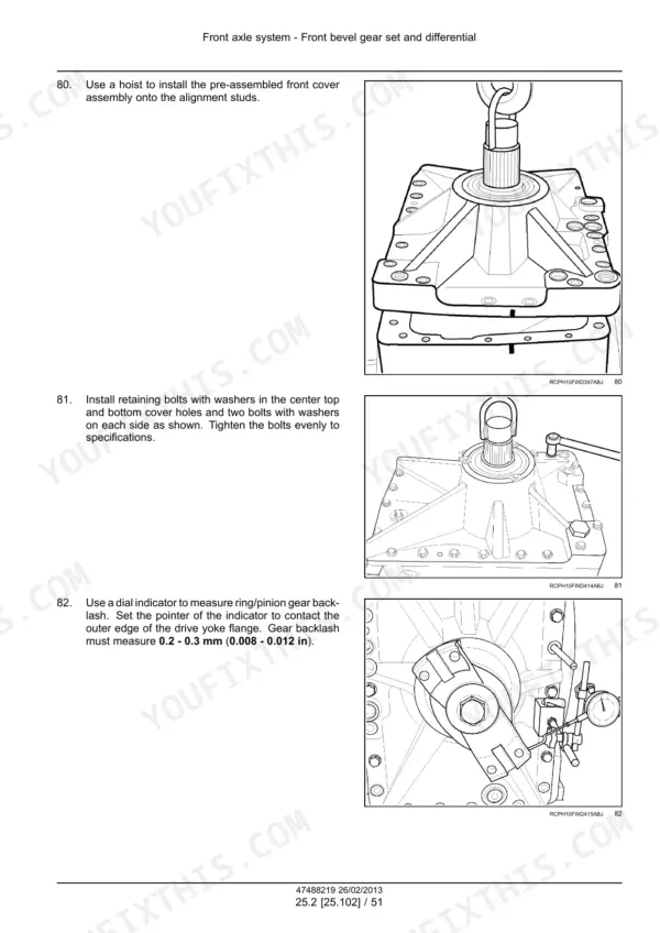
| Front Axle - Bevel Gear Set & Differential - 102 | 850-1111 | Bevel Gear Set Adjustment, Differential and Differential Lock, Pinion Depth and Backlash |
| Front Axle - Final Drives - 310 | 1112-1215 | Planetary Carrier, Wheel Hub and Bearings, Final Drive Seals |
| Rear Axle System - Housing & Carrier | 1216-1291 | Rear Axle Removal and Installation, Axle Shaft Service |
| Rear Axle - Bevel Gear Set & Differential - 106 | 1292-1567 | Crown Wheel and Pinion Adjustment, Differential Lock Pack, Ring Gear Runout |
| Rear Axle - Planetary & Final Drives - 120 | 1568-1671 | Planetary Gear Set, Rear Final Drive Housing, Bearing Preload |
| Power Take-Off (PTO) | 1672-1829 | One-Speed Rear Power Take-Off (PTO) - 110, PTO Gearbox - 220, PTO Clutch and Output Shaft |
| Brakes & Controls | 1830-1895 | Hydraulic Service Brakes - 202, Park Brake, Brake Control Linkage |
| Hydraulic Systems - Composite Schema & Components | 1896-2139 | Hydraulic Schema with Its 54-Item Key, Hydraulic Symbol Tables and Diagram Legends, Pumps, Filters and Reservoir, Load-Sensing System Start-Up Procedure |
| Hitches, Drawbars, Frames & Ballasting | 2140-2169 | Implement Couplings, Drawbar and Hitch Assembly - 110, Ballast Fitting |
| Steering & Wheels | 2170-2249 | Hydraulic Control Components - 200, Steering Pump - 206, Auxiliary Steering - 910, Front and Rear Wheels |
| Cab Climate Control | 2250-2351 | Air Conditioning - 200, Cab Pressurizing System - 300, Refrigerant Handling |
| Electrical - Control Subsystems | 2352-2427 | Fuel Injection System - 010, Transmission Control System - 024, Remote Control Valve Electric Control - 035, Front and Rear Axle Control Systems - 045 and 046, HVAC Control System - 050 |
| Electrical - Harnesses, Connectors & Schematic Frames - 100 | 2428-2769 | Numbered Colour Schematic Frames, Fuses Through Lighting and Power Points, Wire Colour Abbreviations and Circuit Diagram Legend, Harness Prefix Definitions, Fuse and Relay Identification Tables, Connector Location Drawings |
| Electrical - Charging, Lighting & Electronic Modules | 2770-2875 | Rear Three-Point Hitch Electronic Control System - 130, Alternator - 301, Battery - 302, External Lighting - 404, Electronic Modules - 640, SCR Electrical System - 988 |
| Fault Codes (DTC) - Codes 1002 to 2999 | 2876-3349 | Hitch, Transmission and Park Brake Codes, SCR and DEF/AdBlue Codes in the 19xxx Block, Shuttle Lever, Clutch Solenoid and Speed Sensor Codes, Test Steps and Connector Checks per Code |
| Fault Codes (DTC) - Codes 3004 and Above | 3350-3833 | Injector and Rail Pressure Codes, Rear Remote Valve Codes, PTO and Hand Throttle Codes, Automatic Temperature Control Codes |
| Platform, Cab, Bodywork & Decals | 3834-3975 | Engine Shields, Hood Latches and Trims - 102, Pneumatically-Adjusted Operator Seat - 124, Cab - 150, Cab Interior - 151 |
| Special Tool Index | 3976-4015 | Genuine Tool Part Numbers, Tool Illustrations by Section |
New Holland T9 Series Common Problems This Manual Covers
A code number is sitting on the colour display and the operator's book does not explain it.
Look it up in the fault code reference. Codes 1002 to 2999 run from page 2876 to 3349, codes 3004 and above from page 3350 to 3833. Each entry lists the test steps and connector checks for that code, so the diagnosis follows a written sequence instead of guesswork.
Manual Section: Fault Codes (DTC) - Codes 1002 to 2999The steering has gone heavy or wanders, and I cannot tell if it is the pump, the valve block or the pilot unit.
Trace the circuit first on the composite hydraulic schema on page 1902, where the steering valve block, pilot steering unit and steering cylinders are drawn into the full colour circuit. Then work through Steering & Wheels, pages 2170 to 2249, which carries the hydraulic control components - 200, the steering pump - 206 and the auxiliary steering - 910.
Manual Section: Steering & WheelsThe powershift shifts harshly and the shuttle does not take up cleanly.
Check for stored codes first: shuttle lever, clutch solenoid and speed sensor codes are in the fault code reference, pages 2876 to 3349. The transmission control system - 024 is under Electrical - Control Subsystems, pages 2352 to 2427, and if the fault is mechanical, clutch packs, shafts and bearing settings are in Transmission - Powershift Overhaul, pages 234 to 415.
Manual Section: Transmission - Powershift OverhaulA DEF/AdBlue warning has come up and will not clear.
The SCR and DEF/AdBlue codes sit in the 19xxx block of the fault code reference, pages 2876 to 3349, each with its own test steps. The Selective Catalytic Reduction (SCR) exhaust treatment - 500 is in the Engine section, pages 42 to 233, and the SCR electrical system - 988 is under Electrical - Charging, Lighting & Electronic Modules, pages 2770 to 2875.
Manual Section: Engine p. 2876Frequently Asked Questions
There is a fault code on my display. What does the fault code section actually give me?
Pages 2876 to 3833 are a code-by-code reference, split into codes 1002 to 2999 and codes 3004 and above. Each code gets its own entry with test steps and connector checks, so you follow a written sequence instead of swapping parts. The listed coverage runs from hitch, transmission and park brake codes through shuttle lever, clutch solenoid and speed sensor codes, SCR and DEF/AdBlue codes in the 19xxx block, injector and rail pressure codes, rear remote valve codes, PTO and hand throttle codes, and automatic temperature control codes. p. 2876
How are the wiring diagrams organised?
As numbered colour schematic frames in the harnesses and connectors section, pages 2428 to 2769. Frame 01, FUSE 1 TO 14, is at page 2456, drawn to cab fuse/relay module 1 with every fuse named and rated, for example ignition circuit 15.0 A and engine-ECM controller 20.0 A. Wire codes carry gauge and colour, connectors and splices are referenced, and arrows point to the sheet each circuit continues on. The same section holds the wire colour abbreviations, the circuit diagram legend, harness prefix definitions, fuse and relay identification tables and connector location drawings. p. 2428
How do I check that this manual covers my T9?
It covers the T9.390, T9.450, T9.505, T9.560, T9.615 and T9.670. The serial applicability printed on the sheets is [ZCF200001 - ] WE and [ZDF200001 - ] WE, the 2013-on Tier 4 range with SCR and DEF/AdBlue. Compare your tractor's serial number against those two ranges. If it falls at or after ZCF200001 or ZDF200001, the sheets apply to it.
Is there a full hydraulic schematic, or only component drawings?
Both. Page 1902 is a composite colour schema of the whole tractor's hydraulics, with a colour key separating the pump supplies, charge pump flow, return to tank, axle lube and fan drive circuits, and a 54-item numbered key on pages 1900 and 1901. Drawn on it are the auxiliary valve stack, hitch cylinders, PTO dropbox, both axles with their differential lock modules, the steering valve block and cylinders, the pumps, filters and tank, the brake valves with the accumulator, and the hydraulic fan drive. The section around it, pages 1896 to 2139, adds the symbol tables, diagram legends and the load-sensing system start-up procedure. p. 1902
Does it cover a complete powershift overhaul, or only adjustments?
The transmission takes three blocks of the book. Pages 234 to 415 cover removal and installation, clutch packs and shafts, and bearing settings. Pages 416 to 487 cover the external controls - 135 and gearbox internal components - 145. Pages 488 to 795 cover the internal components - 155, with clutch and brake assemblies, shaft and gear inspection limits, and reassembly clearances.
Reviews
There are no reviews yet.