
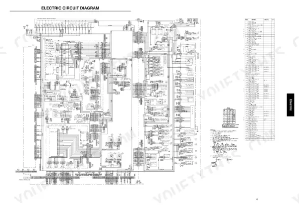
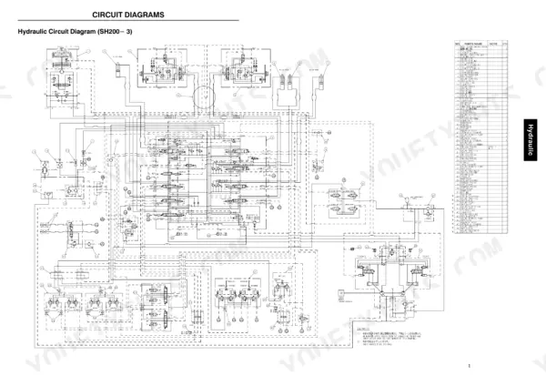
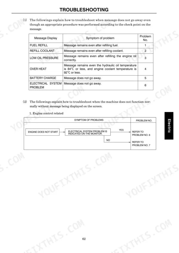
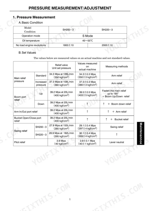
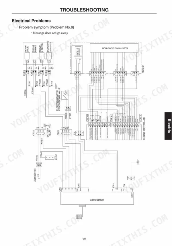
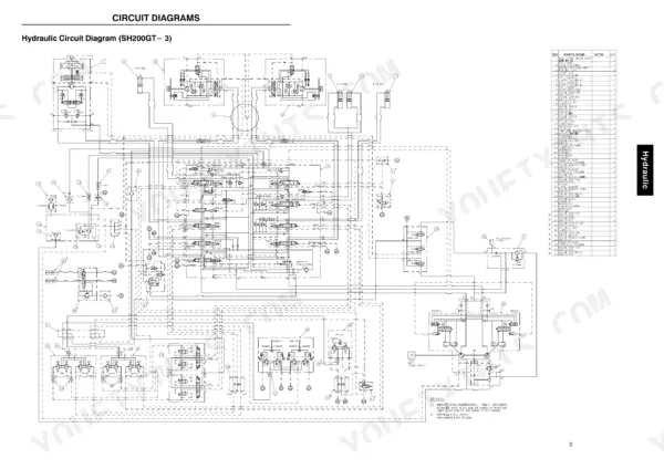
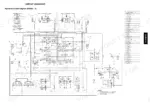
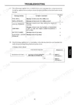
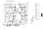
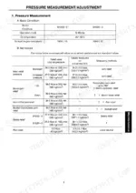
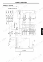
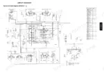
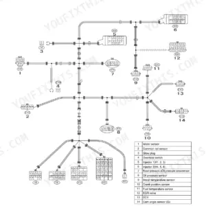
Pilot circuits, main hydraulics, electrics, and pressure adjustment run end to end through this 166-page Sumitomo SH200-3, SH220-3 technical manual PDF for the hydraulic excavator, with parts compatibility noted for SH200-2, SH220-2, and SH200GT-3 machines. Hydraulic circuit diagrams trace oil from the pump through the control valve into the travel, swing parking, boom, arm, and breaker circuits, while pilot hose tables show you which line lands on which port. Close to a third of the book covers the electrical side, from circuit diagrams and engine idling control to fault procedures for low oil pressure, overheating, and alternator trouble. On an SH220-3, H mode current should read 424 mA at maximum and 307 mA at minimum, and main relief, swing motor relief, and pilot pressures come with their measuring and adjustment methods. It's you, the machine, and nobody to call. Bookmarked and text-searchable, this PDF rides along on your laptop or phone to wherever the excavator is parked.
What's Inside This Sumitomo SH200-3, SH220-3 Manual
| System | Pages | Key Topics |
|---|---|---|
| Product Concept | 1-5 | Improved Basic Hydraulic Excavator Functions |
| Specifications | 6-11 | Machine Body Specification, Hydraulic Device, Control Devices |
| Complete Machine Dimensions | 12 | Sh200-3, Sh220-3 |
| Work Range | 13-15 | |
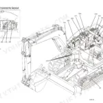
| Layout Drawings | 16 | Main Component Layout |
| Hydraulic Component List | 17-18 | Engine, Hydraulic Pump, Control Valve, Swing Unit, Travel Unit, Boom Cylinder, Arm Cylinder, Bucket Cylinder |
| Full View of Main Components | 19-21 | Hydraulic Pump, Control Valve, Quadruple Solenoid Valves |
| Pilot Hose Connection Diagrams | 22-27 | Pilot Control Line, Pilot P & T Line, Hose Connection Tables |
| Hydraulic System Circuit Diagrams and Operation | 28-62 | Hydraulic Circuit Diagrams, Control Valve Structural Drawings, Travel Circuits, Swing Parking Circuit, Boom/Arm Circuits, Breaker & Crusher Circuits |
| Electric System Components and Functions | 63-113 | Electric Components Layout, Electric Circuit Diagrams, Engine Control, Operation Selection, Idling Control, Breaker Mode, Auto Pre-Heat, Auto Warm-Up |
| Service and Support | 114-138 | Measuring Methods for Electrical Devices, Troubleshooting Procedures, Fuel Refill, Refill Cooling Water, Low Engine Oil Pressure, Over Heat, Alternator, Electrical Problems |
| Pressure Measurement and Adjustment | 139-154 | Pressure Measurement, Pressure Adjustment, Pilot Pressure, Main Relief Pressure, Swing Motor Relief Pressure, Port Relief Pressure |
| Compatibility, Dimensions, and Appendix | 155-166 | Main Parts Compatibility, Bucket Dimensions, Arm Dimensions, Ball-Race Greasing, Long-Life Hydraulic Oil, Units Conversion Table |
Quick Reference Specifications
| Specification | Value | Page |
|---|---|---|
| SH220-3 | ||
| H Mode Current I MAX | 424 mA | p. 76 |
| H Mode Current I MIN | 307 mA | p. 76 |
| Operating Weight | 22,700 kg | p. 6 |
| Engine Output | 121 kw / 2,150 min-1 | p. 6 |
| SH200-3 | ||
| Operating Weight | 19,100 kg | p. 6 |
| Engine Output | 103 kw / 1,950 min-1 | p. 6 |
| All Models | ||
| Fuel Tank Capacity | 340 L | p. 11 |
| Hydraulic Oil Tank Capacity | 120 L | p. 11 |
| Main Relief Pressure (Standard) | 34.3 MPa | p. 7 |
| Main Relief Pressure (Boosting) | 37.3 MPa | p. 7 |
| Pilot Relief Pressure | 3.9 ± 0.1 MPa | p. 145 |
| Cooling Water Capacity | 27 L | p. 11 |
Sumitomo SH200-3, SH220-3 Common Problems This Manual Covers
Sumitomo SH200-3 SH220-3 low engine oil pressure message stays on the monitor after refilling engine oil
Check engine oil level and condition first, following the pre-troubleshooting inspection list on page 127. If the level is correct and the low oil pressure message still shows, work through the Low Engine Oil Pressure troubleshooting procedure step by step before condemning the engine, and confirm the warning against the message display chart on page 126.
Manual Section: Low Engine Oil Pressure TroubleshootingOver heat warning for hydraulic oil or engine coolant temperature showing on the display
Check coolant level with the engine cold and confirm the system against the 27 L cooling water capacity listed on page 11. Verify hydraulic oil level in the 120 L tank too. Then run the Over Heat troubleshooting procedure to separate a hydraulic oil temperature warning from an engine coolant temperature warning.
Manual Section: Over Heat TroubleshootingBattery charge message stays on the display and does not go away while the engine is running
Inspect the battery and electrical devices first using the pre-troubleshooting checks on page 127. Then work through the Alternator troubleshooting procedure to confirm whether the alternator circuit is the cause of the battery charge message. Follow the measuring methods for electrical devices in the Service and Support section before replacing any part.
Manual Section: Alternator TroubleshootingElectrical system problem message on the display with a suspected short circuit in the wiring
Check the circuit against the wiring diagram on page 136 and follow the Electrical Problems troubleshooting procedure to isolate the short. Test the suspect wiring sections using the electrical device measuring methods in Service and Support. Verify the repair by confirming the electrical system problem message clears from the display.
Manual Section: Electrical Problems Troubleshooting p. 136Engine does not start even though the starter motor runs and turns the engine over
Check fuel level first and confirm the fuel refill message is not showing, using the message display chart on page 126. Inspect lubricants, coolant and electrical devices per page 127. Then follow the Engine Start troubleshooting procedure step by step before pulling any components.
Manual Section: Engine Start TroubleshootingPilot relief or main relief pressure reading off specification during a pressure gauge check
Measure pilot relief pressure following the procedure on page 145 and adjust to 3.9 ± 0.1 MPa. Then measure main relief pressure against 34.3 MPa standard and 37.3 MPa with boosting, as listed on page 7. Set the main relief only after the pilot circuit reads correctly, using the adjustment steps starting on page 139.
Manual Section: Pressure Measurement and Adjustment p. 145Frequently Asked Questions
How do I reset the error codes on the Sumitomo SH200-3 or SH220-3?
To clear previous error codes and occurrence time data, turn on the operation mode switch for 10 seconds or more. This action clears the data stored in the diagnosis display (DIAG3 or DIAG6). p. 108
How do I reset the controller settings on the Sumitomo SH200-3?
To reset the controller settings, push the Auto mode SW for 10 seconds while the current setting status is displayed. This will reset all current settings, allowing you to perform the machine model selection again. p. 125
What is the standard main relief pressure for the SH200-3?
The standard main relief pressure for the SH200-3 is 34.3 MPa at 126 L/min. The measured value on an actual machine is 34.3 ± 0.3 MPa (350 ± 3 kgf/cm²). p. 140
What is the tightening torque for the swing motor relief assembly on the Sumitomo SH200-3, SH220-3?
The tightening torque for the relief assembly on the swing motor is 78.5 N·m (8 kgf·m). p. 153
What is the capacity of the hydraulic oil tank for the SH200-3 and SH220-3?
Both the SH200-3 and SH220-3 models have a hydraulic oil tank capacity of 120 L. p. 11
What exactly do I receive with this Sumitomo SH200-3 Technical Manual?
All 166 pages arrive as one searchable PDF at checkout. Read it at the desk, then take the phone out to the machine.
Can I print pages of this Sumitomo SH200-3 manual for my own shop?
Yes. Many buyers print one chapter at a time for their own shop and keep the rest on a tablet.


Reviews
There are no reviews yet.