
This 488-page Takeuchi TB07DW/TB070W Workshop Manual is the factory book for the wheeled compact excavator, and it does not stop at the machine: the last 90 pages are the complete engine workshop manual, so compression checks, injection timing and crankshaft work live in the same PDF. The hydraulic half is where you will spend your time. Every unit is torn down on its own pages: the piston pump (swash plate, rotary group, control piston) on 109-132, the control valve section by section on 133-164, pilot valves on 173-192, cylinders on 193-210 and the slew motor on 211-226. The Clark-Hurth axle and the Rexroth travel motor each carry their own OEM service chapters. Wear limits are spelled out: replace the pump when piston-to-cylinder-block clearance reaches 0.060 mm, torque a PF 1/4 hose union nut to 2.5 kgf-m, and keep a 150-mesh suction filter in the tank. Bookmarked by section and searchable, so you can jump straight to the circuit you are chasing instead of thumbing a paper binder in the mud.
Complete the set for your TB07DW, TB070W
- Parts Catalog: Takeuchi TB070W Parts Catalog
What's Inside This Takeuchi TB07DW, TB070W Manual
| System | Pages | Key Topics |
|---|---|---|
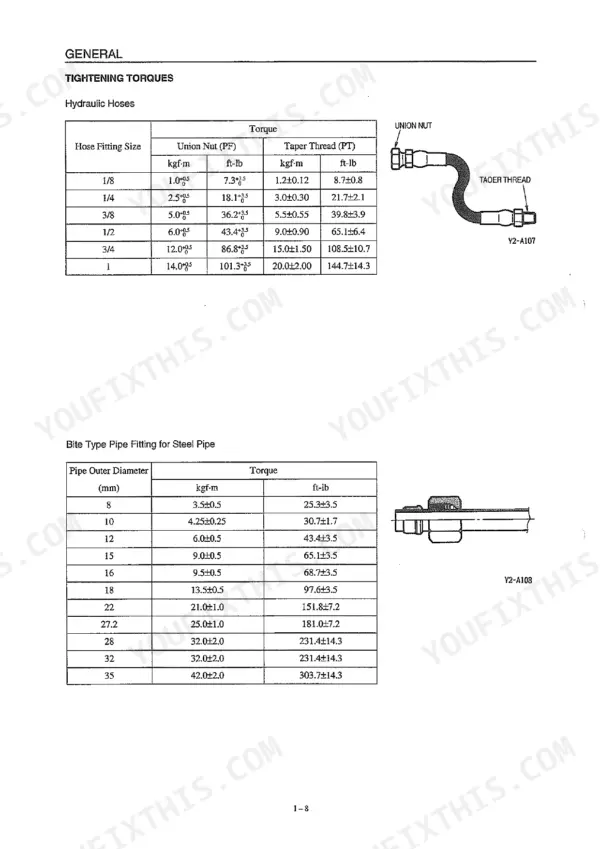
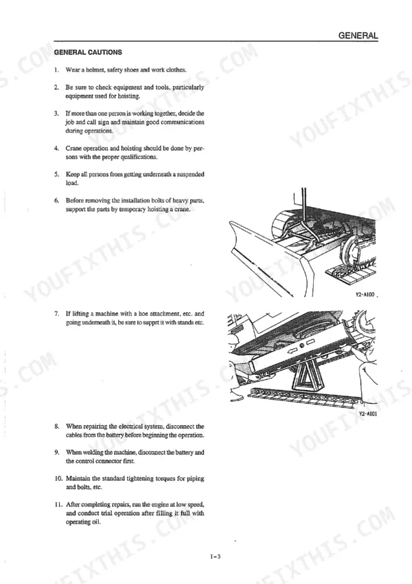
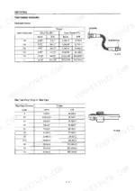
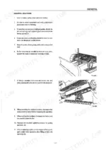
| General | 5-16 | General Cautions, Cautions During Disassembly and Assembly, Cautions During Removal and Installation, Tightening Torque Tables, Hydraulic Hose Union Nut Torques |
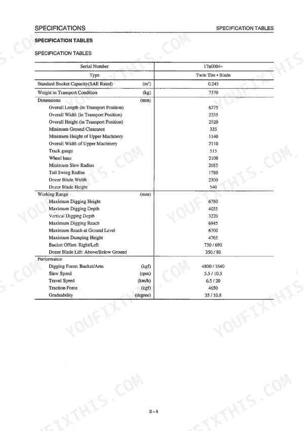
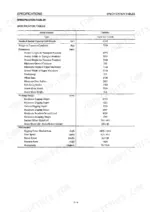
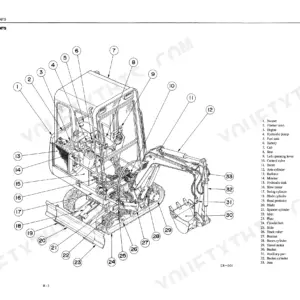
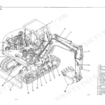
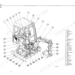
| Specifications | 17-36 | Names of Components, Specification Diagrams, Lifting Capacities, Specification Tables, Fluid Capacities, Machine Dimensions |
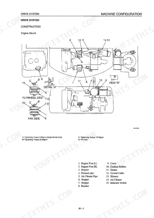
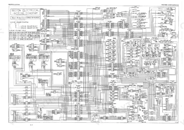
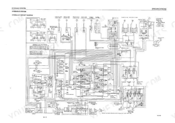
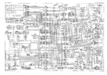
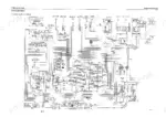
| Machine Configuration | 37-104 | Drive System, Slew System, Upper Frame, Control System, Attachments, Hydraulic System Circuits, Electrical System, Air Conditioner |
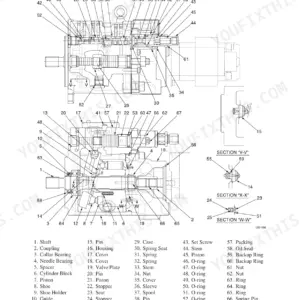
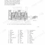
| Hydraulic Pump | 109-132 | Swash Plate, Rotary Group, Control Piston and Spring, Gear Pump, Bearings, Oil Seal and Seal Case, Disassembly and Assembly, Flow Adjustment |
| Control Valve (Mono-Block and 3-Section) | 133-164 | Travel Sections (Left/Right), Boom [1] and [2] Sections, Arm [1] and [2] Sections, Bucket Section, Swing Section, Auxiliary Section, Main Relief Valve Adjustment, Spool and Oil Seal Replacement |
| Solenoid Valve (2- and 3-Section) | 165-172 | Housing and Spool, Solenoid Coil, Spring, Operation with and Without Current, Disassembly and Assembly, Coil Continuity Check |
| Pilot Valve (Working Equipment and Travel) | 173-192 | Casing and Port Plate, Push Rods, Spring Seats and Springs, Bushings, Seal Washers, Disassembly and Assembly, Secondary Pressure Adjustment |
| Cylinder | 193-210 | Piston Rod, Rod Cover and Bushing, Buffer Ring and Rod Packing, Backup Rings, Dust Seal, Cushion Bearing and Seal, Piston Packing, Leak Test |
| Slew Motor | 211-226 | Motor Start and Stop Operation, Relief Valve, Disassembling the Slew Unit, Disassembling the Hydraulic Motor, Brake Piston, Reduction Gear, Inspection and Assembly |
| Axle (Clark-Hurth) | 227-296 | Brake Disc Wear Check and Replacement, Planetary Carrier Removal, Differential Disassembly, Bevel Pinion Preload Shims, Steering Cylinder Removal, Articulation Joint, Special Tools |
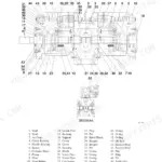
| Travel Motor (Rexroth) | 297-338 | Type Code, Sectional Drawing, General Repair Instructions, Port Plate Disassembly, Rotary Group, Brake Valve, Assembly and Test Instructions |
| Ram Lock Cylinder | 339-346 | Functional Description, Hydraulic Connection Plan, Start-Up and Bleeding, Non-Return Valve Demounting, Fault-Finding, Repair Instructions, Torque Values |
| Swivel Joint | 347-358 | Installation Instructions, Application, Principles of Operation, Seal Replacement, Maintenance |
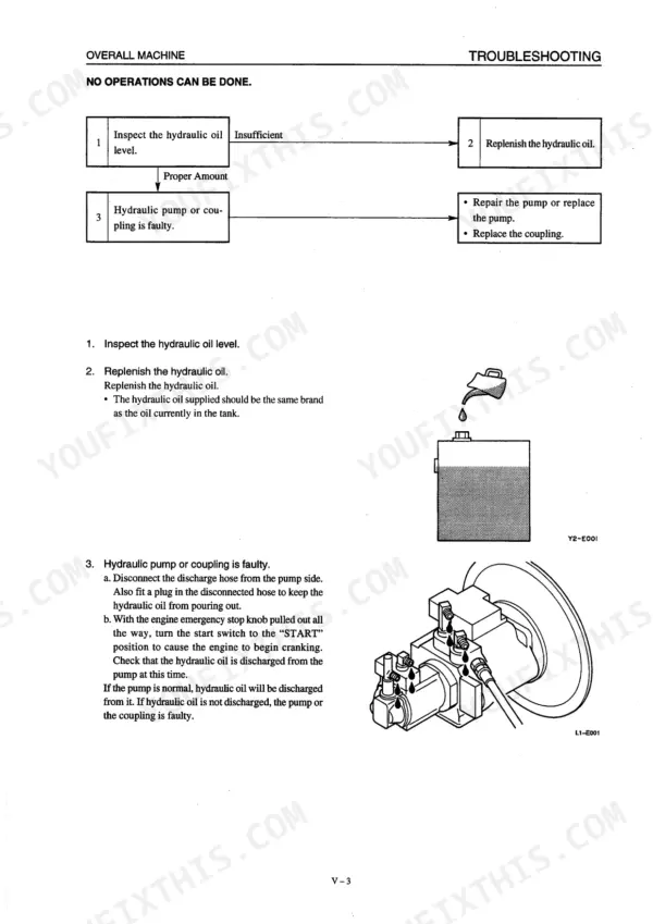
| Troubleshooting | 359-396 | Overall Machine, Slewing, Boom, Arm, Bucket, Boom Swing, Travel, Hydraulic Circuit Diagnosis |
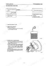
| Engine (Bundled Engine Workshop Manual) | 399-488 | Compression Pressure Check, Fuel Injection Timing Adjustment, Bleeding the Fuel System, Injector Spray Pattern, Cylinder Head and Valves, Rocker Shaft, Camshaft and Gear Backlash, Governor Adjustment, Oil Pump and Oil Pan, Crankshaft End Play, Main Bearing Cap and Plastigage, Service Data, Engine Troubleshooting |
Quick Reference Specifications
| Specification | Value | Page |
|---|---|---|
| Hydraulic Hose Union Nut Torque (PF 1/8) | 1.0 +0.5 kgf-m | p. 14 |
| Hydraulic Hose Union Nut Torque (PF 1/4) | 2.5 +0.5 kgf-m | p. 14 |
| Hydraulic Suction Filter | 150 mesh | p. 69 |
| Hydraulic Return Filter (nominal) | 10 µm | p. 69 |
| Arm Cylinder Bore × Stroke | φ100 × 465–875 st | p. 69 |
| Hydraulic Pump Piston-to-Cylinder-Block Clearance (wear limit) | 0.060 mm or greater = replace | p. 131 |
Takeuchi TB07DW, TB070W Common Problems This Manual Covers
Takeuchi TB070W excavator boom, arm, and bucket functions are completely unresponsive or operating at slow speeds.
Install a gauge on the main control valve and test the main relief valve set pressure. Verify it reaches 280 kgf/cm² as noted on page 27 for this specific model. If the pressure is low, adjust the relief valve or replace the assembly to restore normal operation.
Manual Section: Overall Machine Operations p. 27Visible hydraulic fluid leaks near high pressure hose connections or damp patches around swivel joint fittings.
Inspect the swivel joint housing and hose connections for damaged O-rings. Tighten any loose connection bolts to 20 ~ 25N·m (2.0 ~ 2.5kgf·m) as specified on page 130. After repairs, apply maximum working pressure 5 or 6 times to confirm there is no leakage before returning to service.
Manual Section: Swivel Joint p. 130Hydraulic pump produces severe whining and knocking noises followed by complete system failure and no operation.
Remove the hydraulic pump and inspect the internal components for severe wear. Measure the piston and cylinder block assembly clearance shown on page 131. If the clearance is 0.060mm or greater, rebuild or replace the pump assembly and flush the entire hydraulic system to remove metal debris.
Manual Section: Hydraulic Pump p. 131Engine turns over normally but is extremely hard to start or experiences highly irregular RPM.
Test the fuel delivery system and inspect the fuel filter. Verify the fuel filter overflow valve opening pressure is 1.2 (17) kg/cm² (psi) as detailed on page 404. Drain the water separator and replace the filter element if you find heavy contamination or restricted fuel flow.
Manual Section: Engine Starting & RPM Issues p. 404Frequently Asked Questions
What are the recommended service intervals for the machine's components?
The recommended service intervals vary by component. For Hydraulic Oil, it's every 1,000 hours. Grease fittings should be serviced every 10 hours or every 50 hours. The Slew Pinion Shaft Bearing requires service after the first 250 hours, then every 1,000 hours. For engine oil, the initial change is after 25 hours, and then periodically every 100 hours, at which time the oil filter should also be changed. p. 31
What fluids and capacities does this machine require?
The machine requires various fluids with specific capacities. The Hydraulic Oil Tank Level / Total System is 68/132 liters. The Engine Oil Upper Limit / Lower Limit is 11/9 liters. The Slew Grease Bath capacity is 8500 cc, Slew Pinion Shaft Bearing is 200 cc, and Pump Spline is 100 cc. The Fuel Tank holds 120.2 liters, and the Engine Cooling System capacity is 13 liters. p. 30
How do I troubleshoot if the engine won't start?
If the engine is hard to start, possible causes include a discharged battery, poor connection of connector terminals, faulty starter or starter switch, lack of fuel, or issues with the fuel system components like the feed pump, injection pump, or nozzle. Other causes could be clogged filters, incorrect injection timing, or low compression pressure. It is recommended to check these items as listed in the troubleshooting chart. p. 480
What are the valve clearance specifications for the engine?
The valve clearance specifications for the engine, when hot, are 0.35 mm (0.0138 in) for both the intake valve and the exhaust valve. This clearance should be checked and adjusted using a thickness gauge. p. 407
What are the general tightening torque specifications for bolts and nuts?
General tightening torques for ISO Strength Category 10.9 bolts and nuts vary by size and pitch. For example, an M6 x 1.0 bolt requires 1.0±0.05 kgf-m (7.3±0.3 ft-lb), while an M12 x 1.5 bolt requires 8.9±0.44 kgf-m (64.4±3.1 ft-lb). Special tightening points, such as those with molybdenum disulfide applied, have different values. p. 16
How quickly can I access this Takeuchi TB07DW manual after buying?
A 488-page Workshop Manual in searchable PDF format, available the moment you complete checkout. View on computer, tablet, or phone, with no shipping wait.
Am I free to print this Takeuchi TB07DW Workshop Manual?
Yes. Many mechanics print the section they need for their own shop and bring it to the bench.
Reviews
There are no reviews yet.