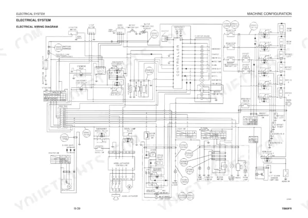
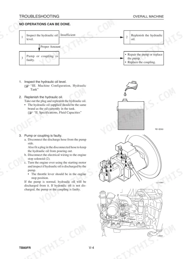
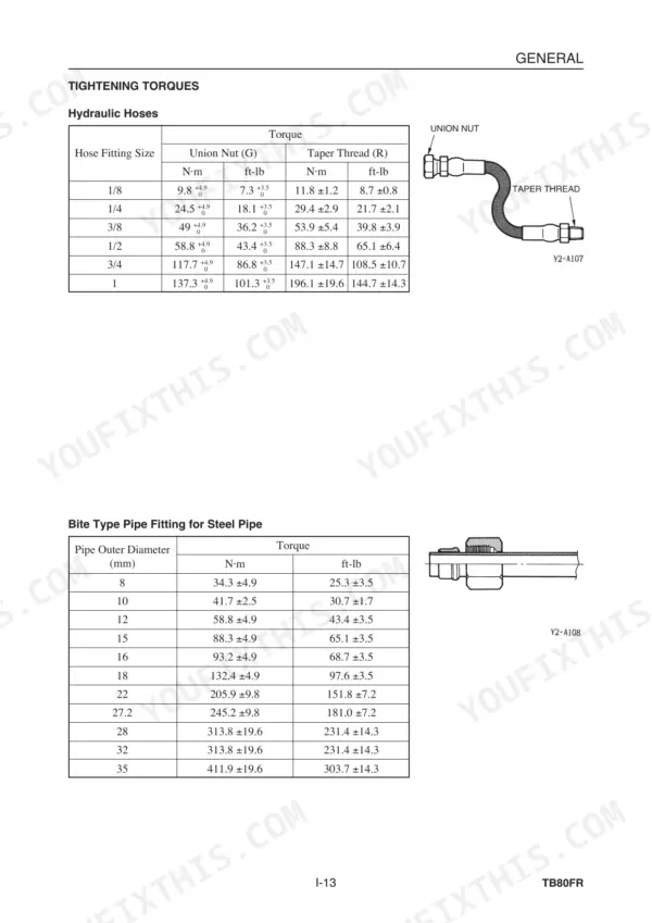
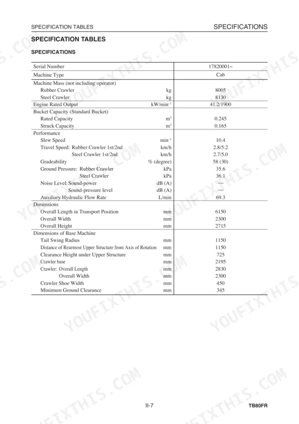
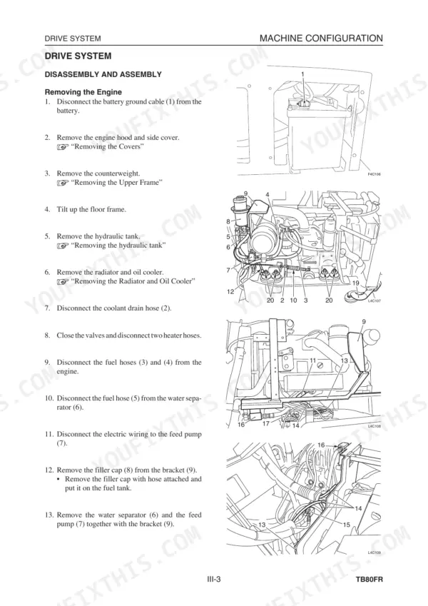
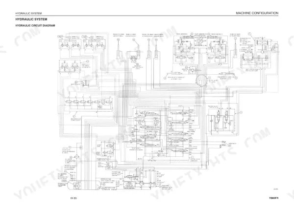
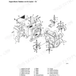
Stop searching for scattered specs because this 520-page Takeuchi TB80FR Workshop Manual PDF (OEM #CL4E000) lays out the factory procedures to rebuild your compact excavator. Open to a massive section of hydraulic schematics, full electrical wiring diagrams, and step-by-step troubleshooting charts covering the slew system, travel motors, and boom assembly. You get detailed teardown steps for the pilot valves, cylinders, and the complete engine block. Secure the 1/4-inch G-type O-ring seal to exactly 34.3 ±4.9 N·m, and follow the factory sequence to adjust the main relief valve set pressure for the arm circuit. Dead machines drain your profits fast. Download this bookmarked file directly to your tablet, search by keyword to find your spec instantly, and drag it straight to the shop floor.
Complete the set for your TB80FR, 4TNE94-98, 4TNE106 (T)
Other edition of this manual
What's Inside This Takeuchi TB80FR, 4TNE94-98, 4TNE106 (T) Manual
| System | Pages | Key Topics |
|---|
| General | 9-24 | Safety Precautions, Cautions During Disassembly and Assembly, Cautions During Removal and Installation of the Hydraulic Units, Cautions During Removal and Installation of Piping |
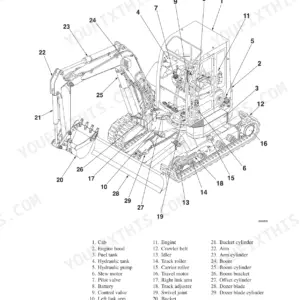
| Specifications | 25-52 | Names of Components, Specification Diagrams, Lifting Capacities, Specification Tables, Mass Tables, Recommended Lubricants |
| Machine Configuration | 53-108 | Drive System, Slew System, Travel System, Upper Frame, Control System, Attachments |
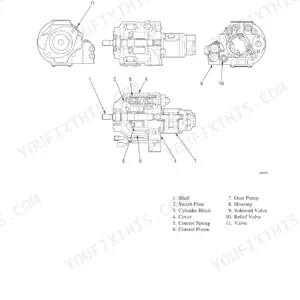
| Hydraulic Units | 109-290 | Hydraulic Pump, Gear Pump, Control Valve, Solenoid Valve, Pilot Valve, Cylinders |
| Troubleshooting | 291-340 | Overall Machine, Machine Travel, Slewing, Boom, Arm, Bucket |
| Engine | 341-520 | General, Troubleshooting, Inspection and Adjustment, Engine Body, Lubrication System, Cooling System |
Quick Reference Specifications
| Specification | Value | Page |
|---|
| Fuel Hoses | Replace fuel hoses periodically. | p. 12 |
| O-ring Seal Type (G) 1/8 | 19.6 ±2.0 N·m | p. 22 |
| O-ring Seal Type (G) 1/4 | 34.3 ±4.9 N·m | p. 22 |
| Hydraulic Tank | 75 kg | p. 89 |
| Hydraulic Oil Pressure (Main Relief Valve Set Pressure) Boom, Arm Adjusting Method | 1. Loosen locknut (2), then begin adjusting pressure by turning setting screw (1). Turning clockwise raises the set pressure. Turning counterclockwise .... lowers the set pressure. 2. In order to keep the setting screw from turning after pressure has been adjusted, tighten the locknut while at the same time holding the setting screw firmly in place. 3. Operate the relief valve once more to confirm that the pressure that has been set it stabilized. | p. 43 |
| Hydraulic Oil Pressure (Slewing Relief Valve Set Pressure) Adjusting Method | 1. Loosen locknut (2), then begin adjusting pressure by turning setting screw (1). Turning clockwise raises the set pressure. Turning counterclockwise lowers the set pressure. 2. In order to keep the setting screw from turning after pressure has been adjusted, tighten the locknut while at the same time holding the setting screw firmly in place. 3. Operate the relief valve once more to confirm that the pressure that has been set it stabilized. | p. 45 |
| Tank capacity | 125 L | p. 89 |
| Cap screw | 29.4 N·m | p. 120 |
| Piston and cylinder block assembly clearance S | 0.05 mm or more | p. 122 |
| If it leaks after the sliding surface has been smoothed, replace the rod packing and other seals | Replace the rod packing and other seals | p. 225 |
| Engine Rated Output | 41.2 kW/1900 min⁻¹ | p. 33 |