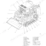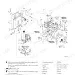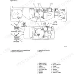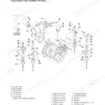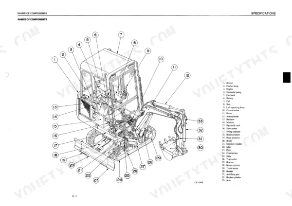
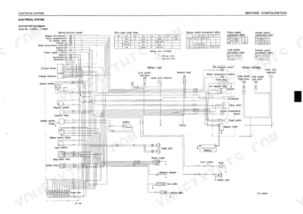
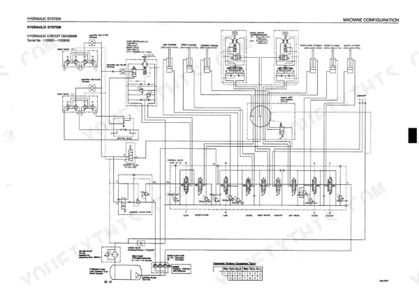
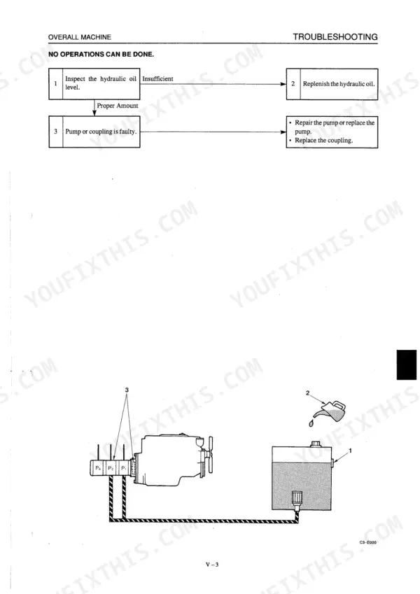
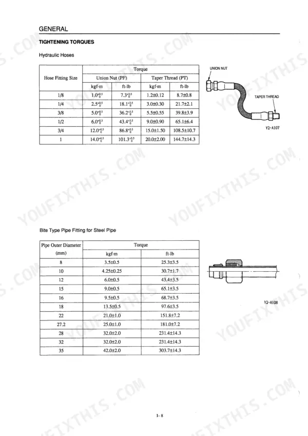
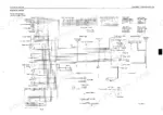
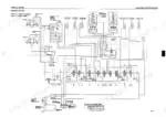
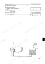
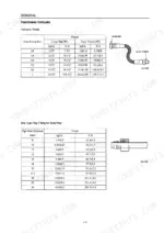
This 328-page Takeuchi TB015 Service Manual (OEM #WC3-101E5) is the workshop manual Takeuchi built for the compact excavator, covering everything from the hydraulic pump down to the swivel joint. Inside you get full wiring diagrams for chasing electrical faults, hydraulic schematics that trace every circuit through the pump, control valve, and cylinders, and a troubleshooting section built around real symptoms: travel, slewing, boom, arm, bucket, and dozer blade faults. You also get exploded views for the drive, slew, and travel systems, plus a torque chart with values by bolt size. Set your M10 x 1.5 bolts to 47.1±2.4 N-m and your M12 x 1.75 bolts to 83.4±4.1 N-m, straight from the factory table on page 16. No more borrowing numbers from a bigger machine's manual and hoping they translate. It's bookmarked by section, so you jump straight to the swivel joint or the pump without hunting, right from your phone in the shop.
Complete the set for your TB015
- Parts Catalog: Takeuchi TB015 Parts Manual
What's Inside This Takeuchi TB015 Manual
| System | Pages | Key Topics |
|---|---|---|
| General | 5-16 | Cautions During Disassembly and Assembly, Cautions During Removal and Installation of the Hydraulic Units, Cautions During Removal and Installation of Piping, Handling of Seals |
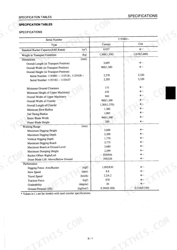
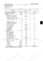
| Specifications | 17-54 | Names of Components, Specification Diagrams, Lifting Capacities, Specification Tables, Weight Tables, Fluid Capacities, Recommended Lubricants, Types of Crawler Belts |
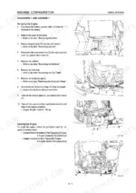
| Machine Configuration | 55-118 | Drive System, Slew System, Travel System, Upper Frame, Control System, Attachments, Hydraulic System, Electrical System |
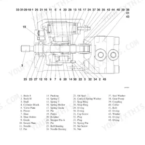
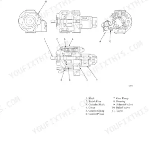
| Hydraulic Units: Hydraulic Pump | 119-132 | Discharge Volume Measurement, Pump Regulator, Gear Pump, Disassembly and Assembly, Parts Use Limits, Troubleshooting |
| Hydraulic Units: Control Valve | 133-150 | Main Relief Valve Pressure Adjustment, Spools and Springs, Port Relief Valves, Disassembly and Assembly, Parts Use Limits, Troubleshooting |
| Hydraulic Units: Control Valve (Sub) | 151-156 | Sub Valve Spools, Blade and Swing Circuits, Disassembly and Assembly, Parts Use Limits, Troubleshooting |
| Hydraulic Units: Pilot Valve | 157-166 | Push Rod and Spool, Return Spring, Special Tools, Disassembly and Assembly, Parts Use Limits, Pilot Pressure Adjustment, Troubleshooting |
| Hydraulic Units: Cylinders | 167-184 | Boom Cylinder, Arm Cylinder, Bucket Cylinder, Blade Cylinder, Disassembly and Assembly, Seal Replacement, Internal Leakage Inspection |
| Hydraulic Units: Travel Motor | 185-216 | Reduction Gears, Valve Assembly, Operation of the Parking Brake, Disassembly and Assembly, Troubleshooting |
| Hydraulic Units: Slew Motor | 217-254 | Reduction Gear, Brake Valve, Timer Valve, Operation of the Parking Brake, Disassembly and Assembly |
| Hydraulic Units: Swivel Joint | 255-268 | Operation, Disassembly and Assembly, Inspection, Seal Replacement, Reassembly |
| Troubleshooting | 269-328 | Overall Machine, Machine Travel, Slewing, Boom, Arm, Bucket, Boom Swing, Dozer Blade |
Quick Reference Specifications
| Specification | Value | Page |
|---|---|---|
| General Tightening Points (Non-lubricated) - M6 X 1.0 | 9.8±0.5 N·m | p. 16 |
| Shaft and Bearing Bore Diameter Interference | 0.008~0.031 | p. 36 |
| Roller and Bearing Outer Diameter Interference | 0.004~0.039 | p. 36 |
| Shaft and Bearing Bore Diameter cleararce | 0.008~0.031 | p. 38 |
| Idler and Bearing Outer Diameter Interference | 0.004~0.039 | p. 38 |
| Plug Tightening Torque | 5~6 kgf·m | p. 39 |
| Socket Bolt Tightening Torque | 0.9~1.1 kgf·m | p. 144 |
| Hydraulic Oil Total System Capacity | 30 l | p. 30 |
Takeuchi TB015 Common Problems This Manual Covers
Takeuchi TB015 hydraulic system loses pressure under heavy load or boom drifts downward during operation.
Inspect the boom cylinder for internal leakage as detailed on page 305. If the boom cylinder rod retracts, the cylinder is leaking internally. Verify the main relief valve set pressure reaches 195 kgf/cm2. Rebuild the cylinder with new seals, coating them lightly with grease before assembly.
Manual Section: V . Troubleshooting p. 305Rubber track tensioner fails to hold grease pressure and loses tension during operation.
Measure the rubber crawler tension to verify it falls within the 52 to 57 mm range shown on page 35. Inspect the track adjuster check valve for damage. Replace faulty seals and tighten the track adjuster check valve to exactly 6 kgf-m torque as specified on page 39.
Manual Section: Ii . Specifications p. 35Boom, bucket, slew, and arm do not move at all, or the operating speed is extremely low.
Check the hydraulic oil total system capacity to ensure it holds exactly 30 liters. Drain the tank and inspect the hydraulic pump seals. Replace all seals with new ones each time the pump is disassembled, coating them lightly with grease as instructed on page 124.
Manual Section: Overall Machine: The boom, bucket, slew and arm do not move at all, or the speed is low p. 124Speed drops in the left or right travel and the machine travels in a wide curve.
Test the travel motor parking brake torque to ensure it releases cleanly and holds at 45 kgfm as listed on page 28. Verify the main relief valve set pressure reaches 195 kgf/cm2. If readings are low, remove the travel motor and inspect the reduction gears for wear.
Manual Section: Machine Travel: Speed drops in the left or right travel, causing the machine to travel in a curve p. 28Frequently Asked Questions
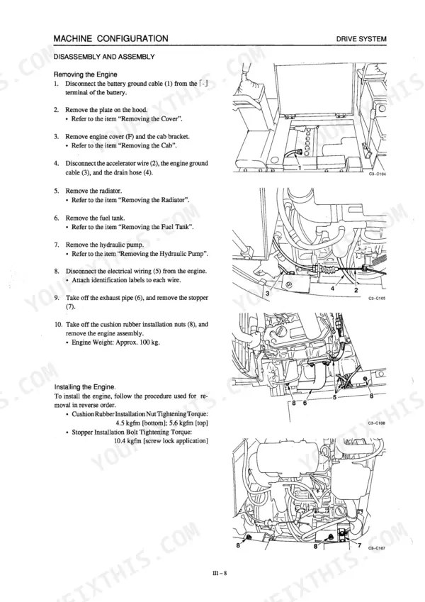
What are the torque specifications for the Takeuchi TB015 engine mount bolts?
When installing the engine, the cushion rubber installation nuts require a tightening torque of 4.5 kgfm for the bottom and 5.6 kgfm for the top. The stopper installation bolt requires a tightening torque of 10.4 kgfm with screw lock application. p. 64
What are the replacement specifications for the Hydraulic pump seals?
When disassembling the hydraulic pump, all seals should be replaced with new ones, coated lightly with grease. It is important to check oil seals for scratches, wear, deformation, or deterioration of rubber's elasticity, and replace if abnormal. Backup rings should also be checked for scaling and cutting and replaced if abnormal. p. 124
What are the replacement specifications for the Main control valve spool?
Main control valve spools and block bodies are specially selected for a precise fit. If any damage, such as scratch marks or non-smooth operation, is found in either of these parts, the entire block assembly must be replaced as a unit. Scratches on the spool's sliding portion or where it contacts seals also necessitate replacement. p. 143
What is the total system capacity for hydraulic oil in the Takeuchi TB015?
The total system capacity for hydraulic oil in the Takeuchi TB015 is 30 liters. The tank level capacity is 21 liters. p. 30
What is the upper limit capacity for engine oil in the Takeuchi TB015?
The upper limit capacity for engine oil in the Takeuchi TB015 is 2.4 liters. The lower limit is 1.4 liters. p. 30
What format is this Takeuchi TB015 manual in?
A 328-page Service Manual in searchable PDF format, available the moment you complete checkout. View on computer, tablet, or phone, with no shipping wait.
Can I print pages of this Takeuchi TB015 manual for my own shop?
Yes. Print individual pages or full chapters for your own shop use, on letter or A4 paper.