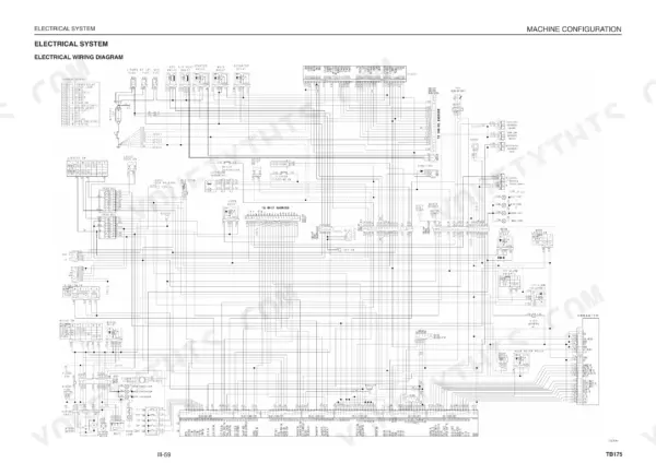
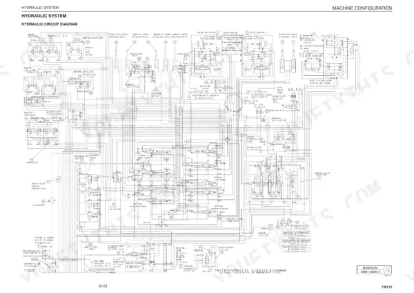
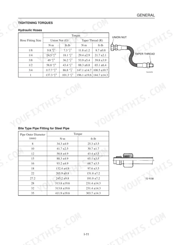
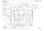
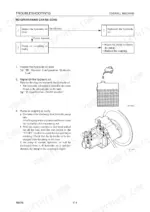
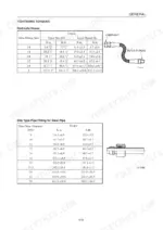
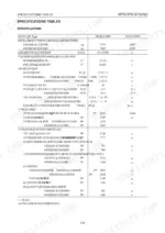
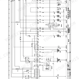
Written for one machine, the Takeuchi TB175 hydraulic excavator, this 488-page workshop manual (OEM ID CL7E002) runs from general cautions through component overhaul and engine diagnostics. Hydraulic schematics in the Takeuchi TB175 service manual PDF trace the circuits from the piston and gear pumps through the control and pilot valves to the cylinders, travel motor and slew motor, and wiring diagrams cover the electrical side. Troubleshooting runs by symptom, from travel to bucket. Fill the hydraulic tank to 68 L and keep engine oil no higher than the 10.2 L upper limit of the pan; M10 coarse bolts take 47.1 ±2.4 N·m. If your job is removing a pump or valve block, the cautions for hydraulic units, piping and seal handling are set out before any teardown begins. Bookmarked by chapter and searchable by text, the file goes with you to wherever the TB175 is working, on a laptop or tablet in the cab.
What's Inside This Takeuchi TB175 Manual
| System | Pages | Key Topics |
|---|---|---|
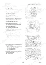
| I . General | 5-18 | Safety Precautions, Disassembly and Assembly, Hydraulic Units, Piping, Seals, Tightening Torques |
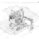
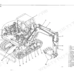
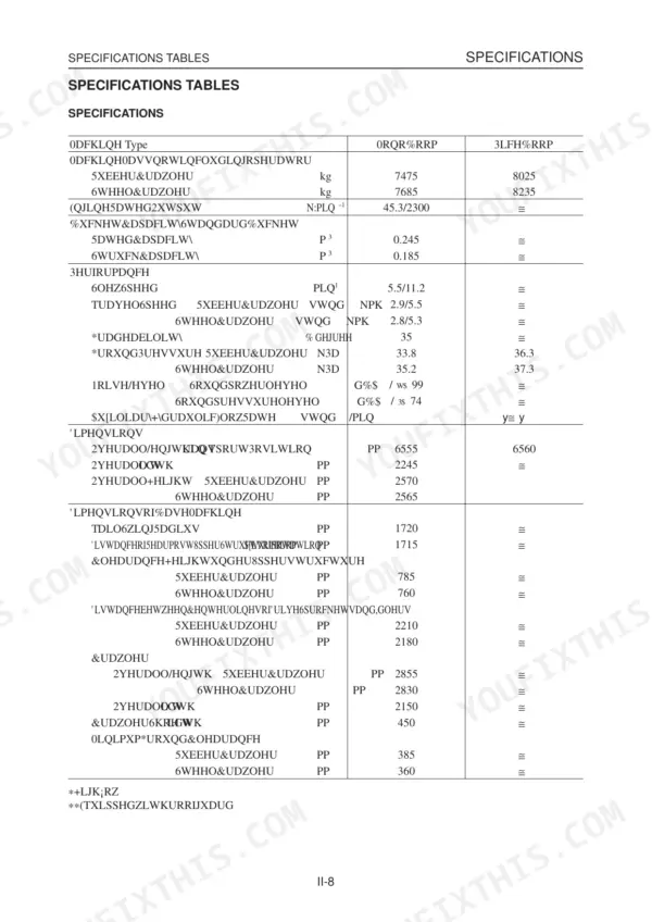
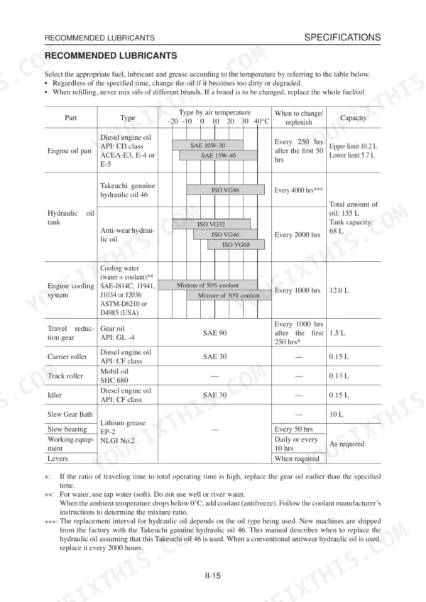
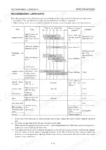
| Ii . Specifications | 19-64 | Component Names, Dimensions, Mass Tables, Lubricants, Crawler Belts, Attachments |
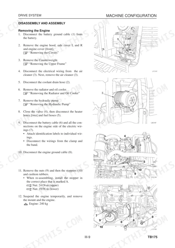
| Iii . Machine Configuration | 65-200 | Drive System, Slew System, Travel System, Upper Frame, Control System, Hydraulic System |
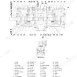
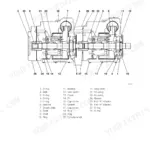
| Hydraulic Pump and Gear Pump | 201-224 | Hydraulic Pump Construction, Piston Pump Operation, Gear Pump Construction, Disassembly and Assembly, Troubleshooting |
| Control Valve (Mono-Block) | 225-250 | Control Valve Construction, Spool Switching, Anti-Drift Valve, Main Relief Valve, Port Relief Valve, Troubleshooting |
| Control Valves (Sectional) | 251-268 | Control Valve Construction, Slew Flow Control Section, Dozer Blade Section, Auxiliary Section, Disassembly and Assembly |
| Pilot Valves | 269-311 | Pilot Valve Construction, Damping Mechanism, Disassembly and Assembly, Pilot Valve (Swing), Pilot Selector, Selector Valves |
| Proportional Control Solenoid Valve and Port Relief Valve | 312-323 | Proportional Control Solenoid Valve Operation, Port Relief Valve Construction, Shut-Off Valves, Differential Pressure Detection |
| Cylinders | 324-344 | Boom Cylinder, Arm Cylinder, Bucket Cylinder, Dozer Blade Cylinder, Tensioning Cylinder, Disassembly and Assembly |
| Travel Motor and Slew Motor | 345-402 | Travel Motor Construction, Reduction Gears, Counterbalance Valve, Slew Motor Construction, Brake Valve, Troubleshooting |
| V . Troubleshooting | 403-454 | Overall Machine, Machine Travel, Slewing, Boom, Arm, Bucket |
| Vi . Engine | 455 | Engine Model, Serial Number, Mounted Engine |
| Engine Trouble Diagnostics Tool and Maintenance Tool | 456-479 | Engine Trouble Diagnostic Tool, Maintenance Tool, T-ECU, ECU, ECM |
| Maintenance Software | 480-488 | Start Menu Configuration, Error Log, Serial Number, Error Code Table |
Quick Reference Specifications
| Specification | Value | Page |
|---|---|---|
| M6 x 1.0 Coarse General Tightening Torque | 9.8 ±0.5 N·m | p. 17 |
| M8 x 1.25 Coarse General Tightening Torque | 22.6 ±1.1 N·m | p. 17 |
| Engine Rated Output | 45.3 kW / 2300 min-1 | p. 26 |
| Hydraulic Tank Capacity | 68 L | p. 33 |
| Engine Oil Pan Capacity (Upper limit) | 10.2 L | p. 33 |
| Engine Oil Pan Capacity (Lower limit) | 5.7 L | p. 33 |
| Travel Reduction Gear Lubricant Capacity | 1.5 L | p. 33 |
| Fuel Tank Capacity | 120 L | p. 34 |
| Hydraulic Pump Rated Pressure (P1, P2) | 27.5 MPa | p. 28 |
| Hydraulic Pump Rated Pressure (P3) | 24.0 MPa | p. 28 |
| Hydraulic Pump Rated Pressure (P4) | 3.4 MPa | p. 28 |
| Main Relief Valve Pressure Setting (Mono-Block) | 27.5 MPa | p. 28 |
Takeuchi TB175 Common Problems This Manual Covers
Takeuchi TB175 excavator hydraulic system no operations can be done, no boom, arm or slew movement
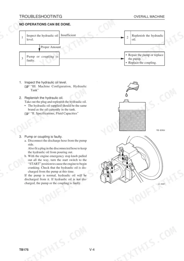
Check the hydraulic oil level and top up with the same brand already in the tank, per page 406. Release all pressure before working on the hydraulic system (page 11). Then disconnect the pump discharge hose, plug it, pull the engine emergency stop knob out fully and crank the engine. If no oil is discharged from the pump, the pump or coupling is faulty; repair or replace it.
Manual Section: Overall Machine Troubleshooting p. 406All operations can be done but there is no power and the hydraulic pump makes noise
Check the hydraulic oil level, then inspect the suction piping for air by applying grease where the noise starts. Check the suction filter for clogging (page 407). Measure main relief pressure against 27.5 MPa. Tighten the set screw gradually; if pressure won't rise after 1/4 turn, the valve is faulty (page 408). For a failed pump, replace the spin filter cartridge and hydraulic oil, cleaning the tank and suction strainer.
Manual Section: Overall Machine Troubleshooting p. 407Right or left travel impossible, one side track will not move under the travel lever
Check pilot output with all hydraulic pressure released before you disconnect any hose (page 11). Disconnect the hose between the travel pilot valve and control valve, plug the valve port and gauge the hose: expect 0 to 3.4 MPa by lever angle (page 411). Verify spool and swivel joint pressure at approx. 27.5 MPa. Push the counterbalance spool by finger; it should move smoothly about 6 mm (page 412).
Manual Section: Machine Travel Troubleshooting p. 411Speed drops in left or right travel and the machine travels in a curve
Check crawler tension and adjust it or remove foreign matter (page 413). When adjusting, never unfasten the grease discharge valve more than one full turn or stand in front of it, and release all hydraulic pressure before disconnecting hoses (page 11). Gauge the tensioning cylinder head hose in 2nd speed; 3.4 MPa means the cylinder is faulty. Swap P1 and P2 discharge hoses: a reversed curve means a faulty pump (page 414).
Manual Section: Machine Travel Troubleshooting p. 413Machine won't accelerate during travel and will not switch to 2nd travel speed
Inspect hydraulic pump P4, the pressure source for 2nd speed, and clean the line filter (page 415). Check pilot relief pressure. Test the travel speed switch for continuity with it ON, then press the 2nd speed solenoid valve and feel for spool vibration when the switch turns ON (page 416). Release all pressure before disconnecting hoses (page 11), then gauge the swivel joint hose at the 2nd speed control valve for 3.4 MPa.
Manual Section: Machine Travel Troubleshooting p. 415No slewing can be done and the turntable will not swing in either direction
Check pilot output with all hydraulic pressure released before disconnecting hoses (page 11). Gauge the slew pilot valve hose for 0 to 3.4 MPa by lever angle, then verify slew spool output against 24.0 MPa (page 419). Measure both slew relief valves; adjust the set pressure or replace the valve if it won't rise. Separate the slew motor and try turning the turntable: stuck means a faulty slew bearing, free means a faulty slew motor (page 420).
Manual Section: Slewing Troubleshooting p. 418Frequently Asked Questions
How do I diagnose TB175 wiring problems?
To diagnose wiring problems, you can use the Takeuchi maintenance software. Connect the laptop to the machine using the dedicated USB cable (Part No. 17301-42720) and the maintenance connector. You can then monitor error logs, check controller serial numbers, and view system data as described on pages 480-487. p. 480
What is the replacement interval for the hydraulic oil on the Takeuchi TB175?
The replacement interval for hydraulic oil depends on the type of oil used. When using Takeuchi genuine hydraulic oil 46, the interval is every 4000 hours. If a conventional anti-wear hydraulic oil is used, it should be replaced every 2000 hours. p. 33
What is the tightening torque for the main relief valve on the Takeuchi TB175?
The tightening torque for the main relief valve on the control valve (mono-block) is 49 to 54 N·m. p. 242
How do I bleed air from the hydraulic cylinder?
To bleed air from the hydraulic cylinder, start the engine and let it idle for approximately 5 minutes. With the engine running at slow speed, extend and retract the cylinder 4 or 5 times, moving the piston rod to a position 100 mm before the end of the stroke. Then, with the engine at top speed, repeat the operation and move the piston rod to the stroke end to apply relief. p. 336
What is the fuel tank capacity of the Takeuchi TB175?
The fuel tank capacity for the TB175 is 120 liters. p. 34
Will this Takeuchi TB175 Service Manual download right away?
Straight to your device: 488 pages of searchable Service Manual, downloadable the moment payment goes through.
Can I print a copy of this Takeuchi TB175 Service Manual for the shop?
Yes. It prints from any PDF reader, so run off the pages you need for your own repair work.