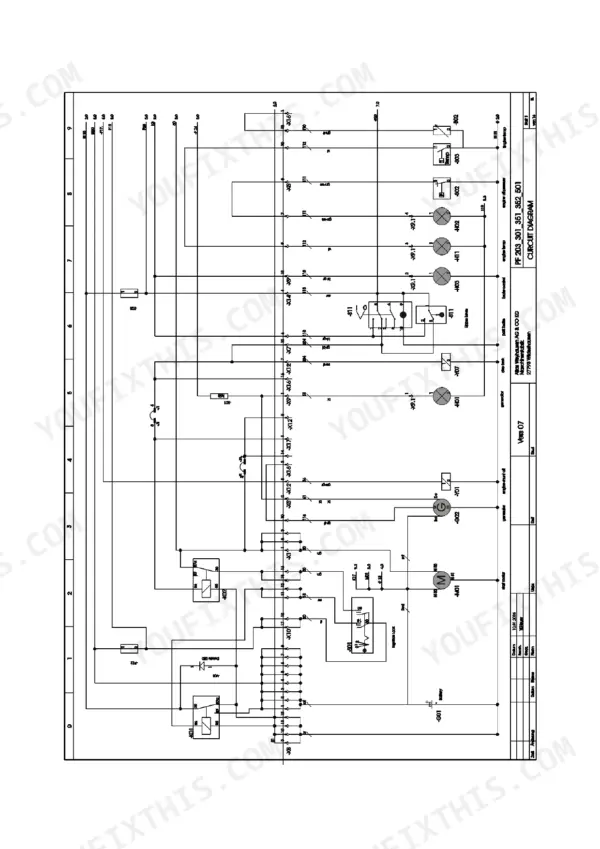
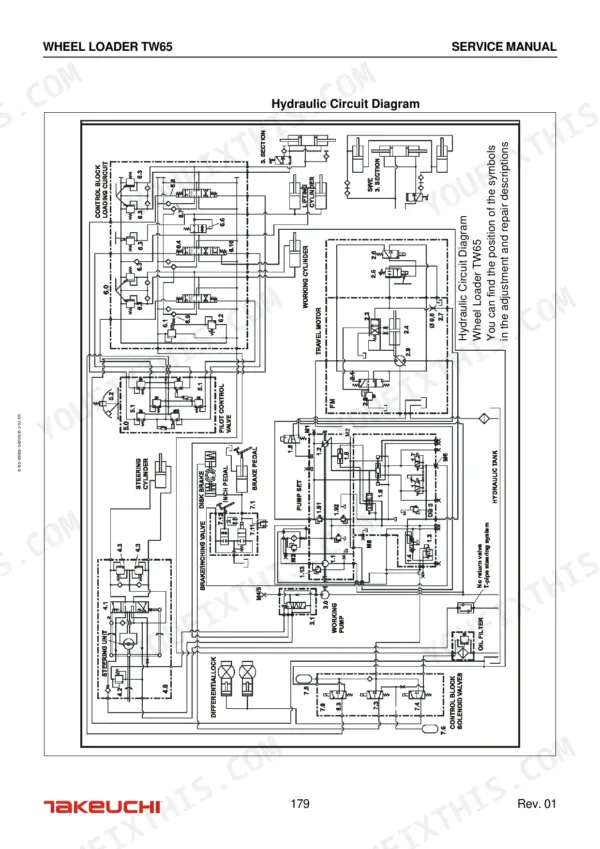
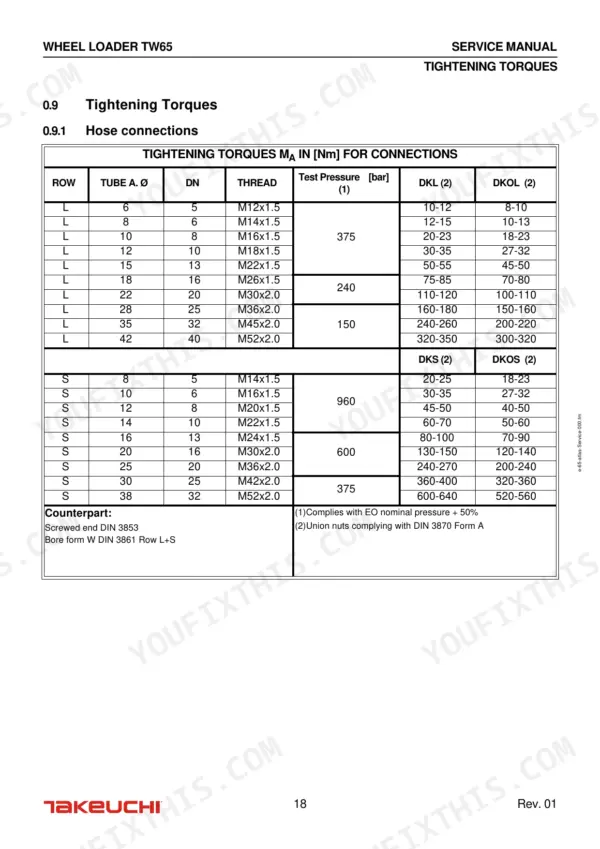
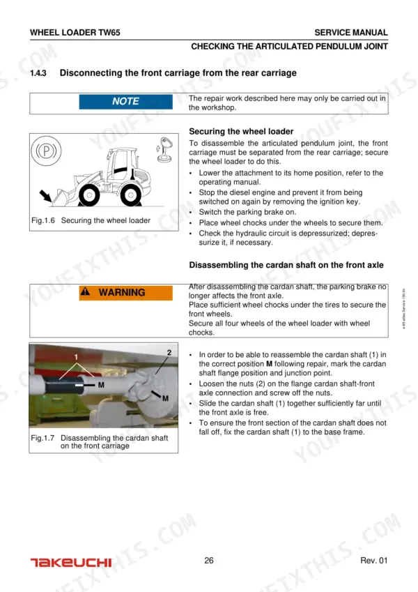
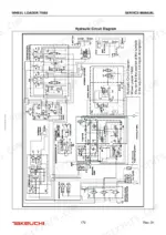
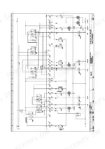
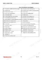
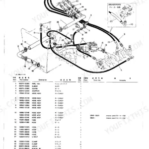
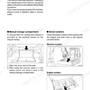
Securing the wheel loader prior to beginning work is the first job laid out in this 308-page Takeuchi TW65 service manual PDF, OEM ID 8015739, written for the TW65 wheel loader from the articulated pendulum joint through to the operator's cab. The hydraulic circuit diagram traces the travel pump, charge pump, travel motor, steering unit, inching valve and priority valve, while the electrical circuit diagrams map the fuses, relays, preheat relay, starter motor and control board. Most chapters carry fault, cause and solution tables. Confirm the pressure limitation valve opens at 230 bar, and tighten hydraulic hose connections to 85 + 5 Nm where the procedure calls for it. If your parts order includes a control unit timing belt or foot brake laminated disks for the rear axle, you have the replacement procedure for each one here. Paid for once, the bookmarked, text-searchable file stays yours to keep for this TW65.
What's Inside This Manual
| System | Pages | Key Topics |
|---|
| Preface | 3-4 | Technical Standards, Safety Regulations, Operating Instructions |
| Introduction | 9-22 | User Information on the Service Manual, Breakdown of Assembly Groups and Chapter Overview, Technical Description of the Wheel Loader |
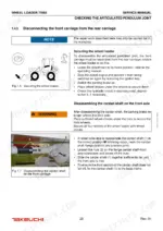
| Front and Rear Carriage | 23-46 | Front Carriage, Repairing the Front Carriage |
| Hoisting Gear | 47-58 | Operating Faults and Solutions, Maintenance Work (Greasing the Hoisting Gear) |
| Hydraulic System | 59-176 | Breakdown of Assembly Groups, Technical Data, Faults, Causes and Corrective Measures, Setting Instructions |
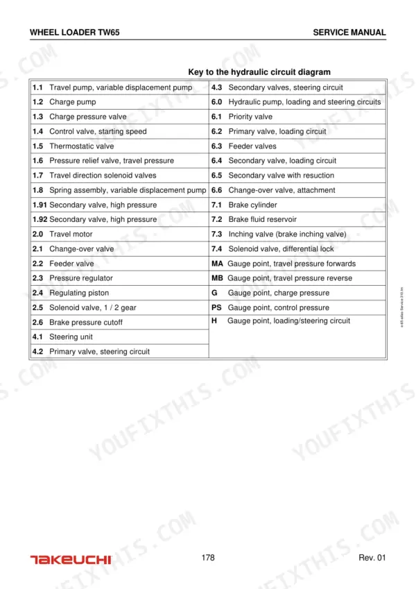
| Appendix to Chapter 3: Hydraulic Circuit Diagram | 177-180 | Travel Pump, Charge Pump, Travel Motor, Steering Unit, Inching Valve, Priority Valve |
| Electrical System | 181-198 | Overview of Fuses and Relays (Lighting), Operating Faults, Maintenance Procedures, Setting Instructions |
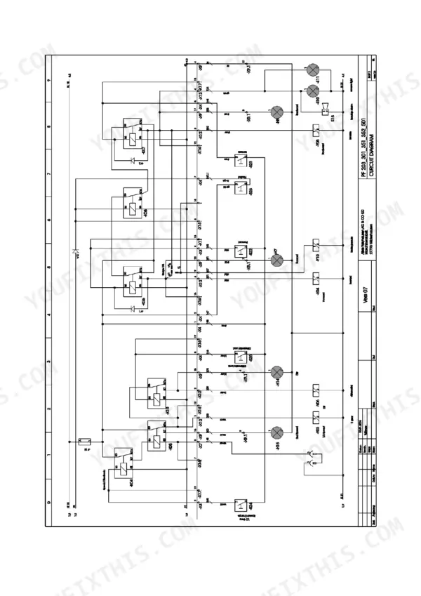
| Appendix to Chapter 4: Electrical System Circuit Diagrams | 199-214 | Fuses, Relays, Lighting, Preheat Relay, Starter Motor, Control Board |
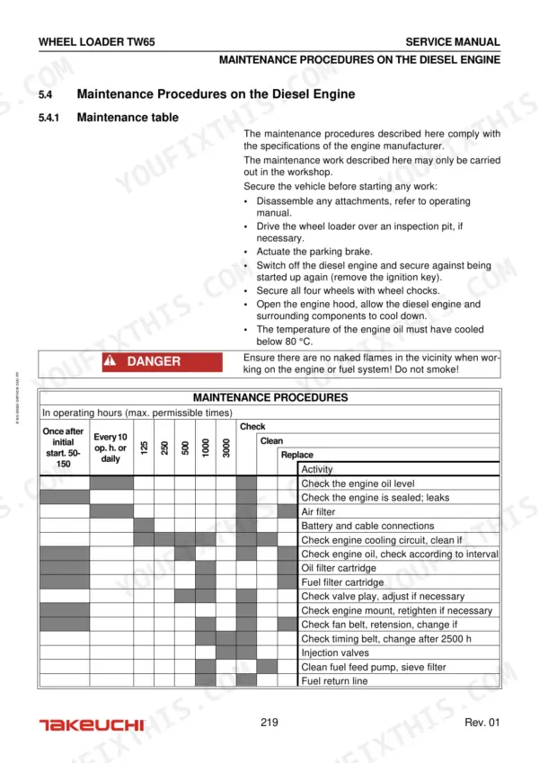
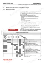
| Diesel Engine | 215-248 | Breakdown of Assembly Groups, Technical Data (Fuel, Engine Oil, Engine Electrical System), Faults, Causes, Solutions (Faults, Causes and Solutions Related to the Diesel Engine) |
| Axles and Brakes | 249-282 | Operating Faults and Solutions, Maintenance Work, Axles (Lubricants and Filling Quantities, Checking the Axle Oil Levels, Checking and Changing the Brake Fluid) |
| Operator's Cab | 283-302 | Breakdown of Assembly Groups, Operating Faults and Solutions, Maintenance Work (Cleaning Work, Monthly Maintenance, Checking Fill Levels) |
| Table of Topics | 303-308 | Axle Repair, Hydraulic Cylinder Repair, Diesel Engine Maintenance, Electrical System Repair, Steering Circuit Repair, Hoisting Gear Maintenance |
Quick Reference Specifications
| Specification | Value | Page |
|---|
| Pressure limitation valve opening pressure | 230 bar | p. 63 |
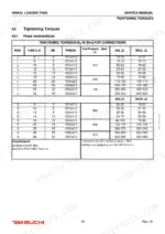
| Tightening torque for L-series hose connections (Tube A. Ø 6, DN 5, M12x1.5) | 10-12 Nm (DKL), 8-10 Nm (DKOL) | p. 18 |
| Tightening torque for L-series hose connections (Tube A. Ø 8, DN 6, M14x1.5) | 12-15 Nm (DKL), 10-13 Nm (DKOL) | p. 18 |
| Engine oil volume with filter | 10.5 liter | p. 216 |
| Engine Power Output | 43 kW (59 PS) | p. 216 |
| Nominal Engine Speed | 2300 min-1 | p. 216 |
| Fuel Capacity | 100 l | p. 216 |
| Battery Capacity | 12 Volt/88 Ah | p. 216 |
| Starter Motor Power | 12 Volt/2.3 kW | p. 216 |