
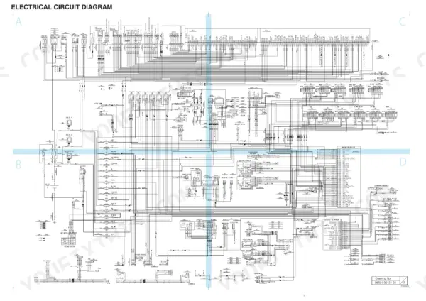
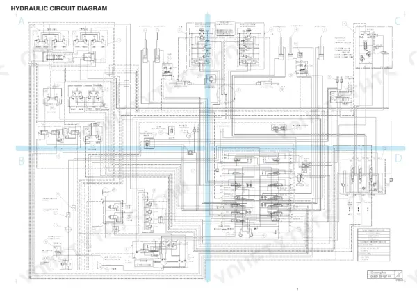
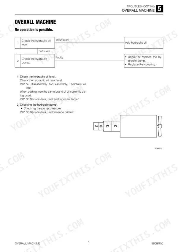
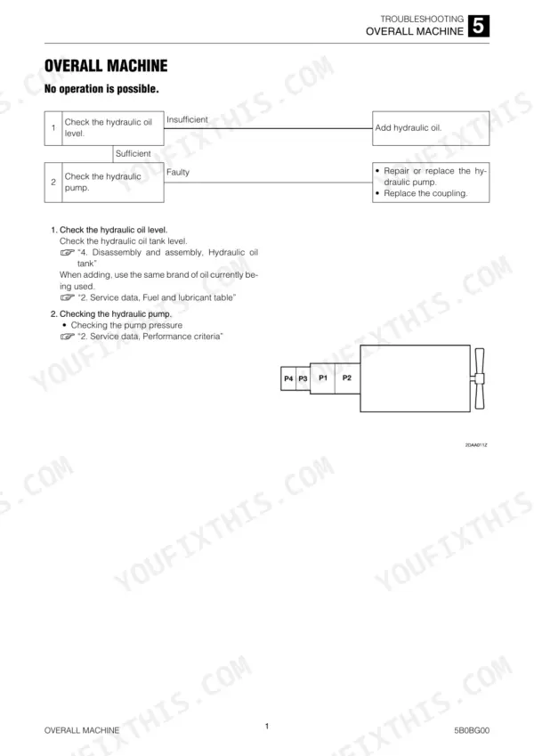
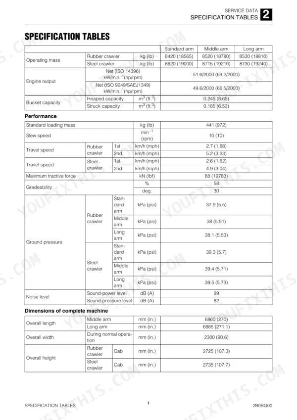
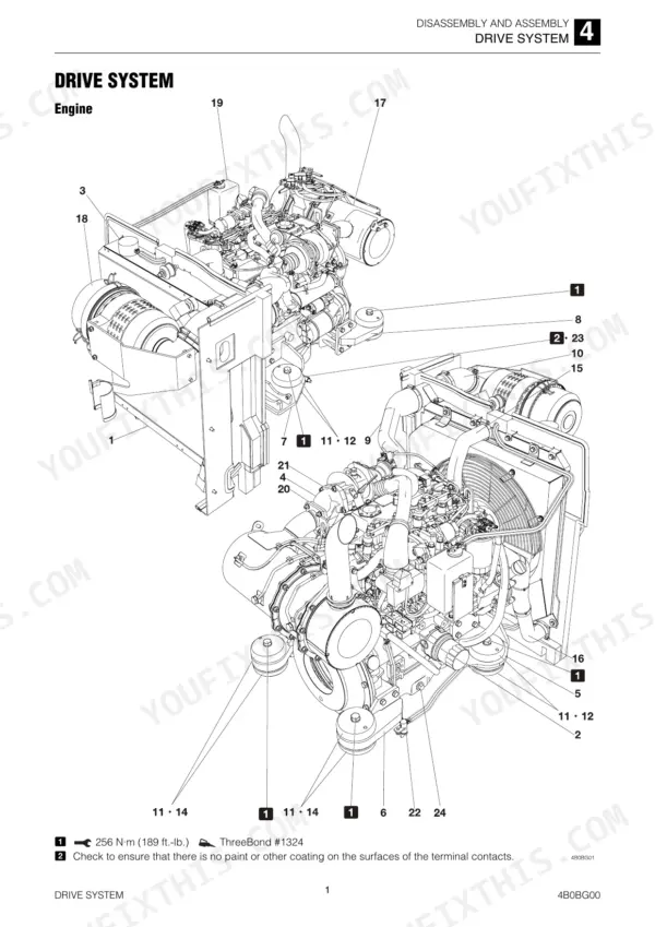
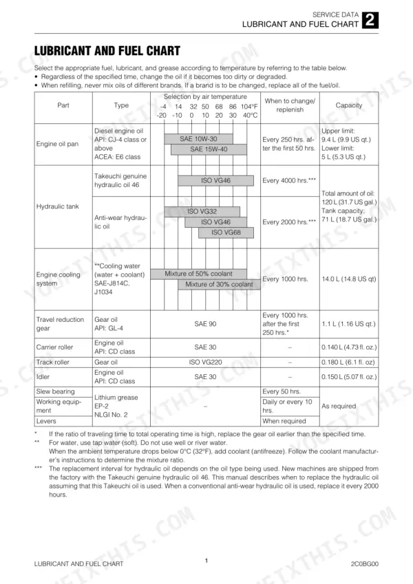
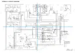
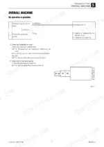
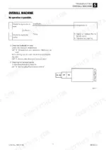
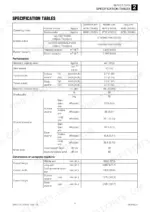
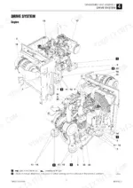
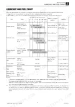
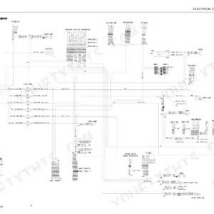
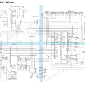
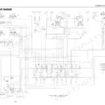
The Takeuchi TB280FR service manual PDF (OEM ID CL9E002) takes this hydraulic excavator apart across 528 pages, from crawler removal and track rollers to the slew bearing, swivel joint and travel motor. Wiring diagrams trace the electrical circuits, and hydraulic schematics follow oil from the pump through the control valve, pilot valves and proportional solenoid valves. Disassembly and assembly fills the largest share of the book, covering the boom and arm cylinders, slew reduction gears and parking brake, while a long troubleshooting section sorts faults by traveling, slewing, boom and auxiliary hydraulics. Replace a track roller once it wears from its 120 mm standard to the 116 mm allowable limit, and hold a 3/8 hose union nut to 49.0 ± 4.9 N·m. The cylinder is apart, the crew is waiting, and you are one number short. Your copy is bookmarked and text-searchable on screen, and it prints cleanly, so the pages you need can go to the bench and take the grease.
What's Inside This Takeuchi TB280FR Manual
| System | Pages | Key Topics |
|---|---|---|
| Safety | 3-12 | Safety Precautions |
| Service Data | 13-80 | Dimensional Drawing, Specification Tables, Performance Criteria, Tightening Torque |
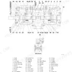
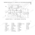
| Function | 81-142 | Hydraulic Pump, Control Valve |
| Drive and Travel Systems | 143-164 | Drive System, Travel System, Crawler Removal, Crawler Installation, Carrier Roller, Track Roller |
| Slew Equipment and Upper Frame | 165-180 | Slew Equipment, Slew Motor, Slew Bearing, Swivel Joint, Upper Frame |
| Operating Devices and Attachments | 181-210 | Operating Devices, Control Levers, Attachments, Hoe Attachment, Bucket, Boom, Dozer Blade |
| Hydraulic Components (Tank, Pump, Control Valve) | 211-243 | Hydraulic Tank, Hydraulic Pump, Control Valve, Relief Valve, Overload Relief Valve |
| Control Valves (Slew, Blade, Auxiliary) and Pilot Valves | 244-275 | Slew Control Valve, Blade Control Valve, Auxiliary Line Piping, Pilot Valve, Solenoid Valve |
| Cylinders and Travel Motor | 276-350 | Proportional Control Solenoid Valve, Auxiliary Line Piping, Cylinders, Travel Motor, Parking Brake |
| Slew Motor and Swivel Joint | 351-379 | Slew Motor, Reduction Gears, Hydraulic Motor, Relief Valve, Timer Valve, Swivel Joint |
| Troubleshooting | 380-439 | Overall Machine, Traveling, Slewing, Boom, Auxiliary Hydraulics |
| Other | 440-528 | Maintenance Software Manual, Air Conditioner System |
Quick Reference Specifications
| Specification | Value | Page |
|---|---|---|
| Maximum torque | 283 to 308 N·m (208.7 to 227.2 ft.-lb.) | p. 19 |
| Hydraulic hose union nut (G) 3/8 | 49.0 ± 4.9 N·m | p. 39 |
| Track roller Standard dimension | 120 mm | p. 144 |
| Track roller Allowable value | 116 mm | p. 144 |
| Internal leak limit | 1 mL (0.034 fl. oz) in three minutes | p. 317 |
| AUX1 slide switch voltage error (Voltage high) | 4.8 V or above | p. 423 |
| Engine Oil Pan Capacity (Upper limit) | 9.4 L | p. 25 |
| Hydraulic Tank Capacity (Total amount of oil) | 120 L | p. 25 |
| Engine Cooling System Capacity | 14.0 L | p. 25 |
| Travel Reduction Gear Oil Capacity | 1.1 L | p. 25 |
| Main relief valve pressure setting | 27.5 MPa | p. 20 |
| Pilot pressure | 3.5 MPa | p. 29 |
Takeuchi TB280FR Common Problems This Manual Covers
Takeuchi TB280FR excavator all systems operate but the machine has insufficient power on every function
Check the overall machine troubleshooting steps starting before you open up the pump. Measure main relief pressure against the 27.5 MPa setting listed on page 20, then verify pilot pressure reaches 3.5 MPa. Confirm both readings before you replace any hydraulic component on this machine.
Manual Section: Overall MachineAUX1 or AUX2 auxiliary line not receiving prescribed pressure at the attachment
Test the AUX1 and AUX2 slide switch signal voltages following page 423. Compare readings against the 4.8 V high and 0.2 V low error thresholds and the 2.2 V to 2.8 V neutral position window. Then check PWM output on page 424, where current 200 mA above or below target logs an output error.
Manual Section: Auxiliary Hydraulics p. 423Machine will not travel right or left, veers to one side, or won't shift into 2nd speed
Check which side is affected first: run each track alone and note whether it stops, veers, or refuses 2nd speed. Work through the Traveling troubleshooting steps, then inspect the travel motor and parking brake following the procedures in the section starting on page 318. Verify pilot pressure reaches 3.5 MPa from page 29 before pulling the motor.
Manual Section: TravelingUpper structure won't slew, slews slowly, or overruns past the stopping point
Work through the Slewing troubleshooting steps before pulling parts. Inspect the slew motor, its relief valve, timer valve and reduction gears following the procedures beginning on page 351. Check the slew control valve too, covered in the section starting on page 244. Verify pilot pressure against the 3.5 MPa value on page 29.
Manual Section: SlewingTrack roller measuring worn below the allowable dimension on the crawler undercarriage
Measure each track roller against the 120 mm standard dimension on page 144 and replace any roller at or below the 116 mm allowable value. Remove the crawler following the service procedures, then torque track roller bolts to 158 N·m (117 ft.-lb) per page 160, the same value page 161 gives for steel crawler rollers.
Manual Section: Drive and Travel Systems p. 144Hydraulic piston pump making noise, running hot, or failing to build pressure
Check the hydraulic tank oil level first; the system holds 120 L total per page 25. Inspect the piston pump for oil leaks and insufficient discharge using the Piston Pump troubleshooting steps, then measure main relief pressure against 27.5 MPa on page 20. Pump service procedures start on page 211.
Manual Section: Piston PumpFrequently Asked Questions
What is the torque specification for the engine mounting bolts on the Takeuchi TB280FR?
The engine mounting bolts for the Takeuchi TB280FR must be tightened to 256 N·m (189 ft.-lb.) using ThreeBond #1324 thread-locking compound. p. 149
What are the replacement specifications for the hydraulic return filter on the Takeuchi TB280FR?
The hydraulic oil filter is a glass fiber filter paper-type with a filter precision of BETA 10 = 6, located in the return circuit inside the hydraulic tank. p. 20
What is the procedure for clearing past malfunction codes using the maintenance software?
To clear past malfunction codes, use the 'Clear Error Codes' function within the Engine side error codes section of the Maintenance Software. This function is specifically designed to read out and clear past malfunction codes. p. 464
What is the correct engine oil capacity for the Takeuchi TB280FR?
The engine oil pan capacity for the Takeuchi TB280FR is 9.4 L (9.9 US qt.) for the upper limit and 5 L (5.3 US qt.) for the lower limit. p. 25
What is the specified tightening torque for the hydraulic hose union nuts on the Takeuchi TB280FR?
The tightening torque for hydraulic hose union nuts varies by size. For example, a 1/8 size nut requires 9.8 N·m (7.3 ft.-lb.), while a 1 size nut requires 137.3 N·m (101.3 ft.-lb.). p. 38
Is this Takeuchi TB280FR manual a download or a disc?
A single searchable PDF file of 528 pages, downloadable right after payment. Nothing ships, nothing waits in the mail.
Am I free to print this Takeuchi TB280FR Service Manual?
Yes. Print a single page or a chapter for your own shop use, on letter or A4.
Reviews
There are no reviews yet.