

Within the hour you could have a gauge on the boom circuit with the oil at 50°C to 60°C (122°F to 140°F), checking for 27.5 MPa (3989 psi). This book shows which locknut to loosen and which way to turn the setscrew. Clockwise raises the set pressure.
It covers the TB295W from serial 190100003~. Takeuchi's own chapters cover the pumps, control valves, pilot valves, cylinders, slew motor and swivel joint. The Dana Axle 212 and Axle 112 manuals are bound in, along with the Sauer-Danfoss Series 51 travel motor and H1 HST pump books. It has no Isuzu engine overhaul section.
While a wheeled excavator sits with a code on the dash, the crew around it isn't earning. The error-code tables take you straight to the circuit at fault. The teardown chapters show you which seal, bushing or valve part to order before you phone the dealer.
What's Inside This Takeuchi TB295W Manual
| System | Pages | Key Topics |
|---|---|---|
| Safety | 1-13 | Safety Alert Symbols, Safety Precautions, Hazardous Materials, Hydraulic Pressure Release, Battery and Tire Handling, Cautions When Disassembling and Connecting Hoses |
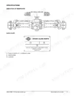
| Service Data: Specifications, Capacities, Performance Criteria and Tightening Torque | 14-50 | Dimensional Drawing, Specification Tables (Isuzu 4JJ1 Engine, Hydraulic System, Travel, Working Range), Table of Masses, Lubricant and Fuel Chart, Standard Values Table (Engine Speeds, Relief Pressures), Pressure Measuring and Adjusting Methods, Bolt and Hose Torque Tables |
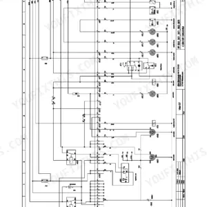
| Hydraulic Circuit Diagrams | 51-62 | Full-Machine Hydraulic Circuit Diagram (Mono Boom and Two-Piece Boom), Control Valve Bank, Pumps, Travel, Slew and Steering Circuits |
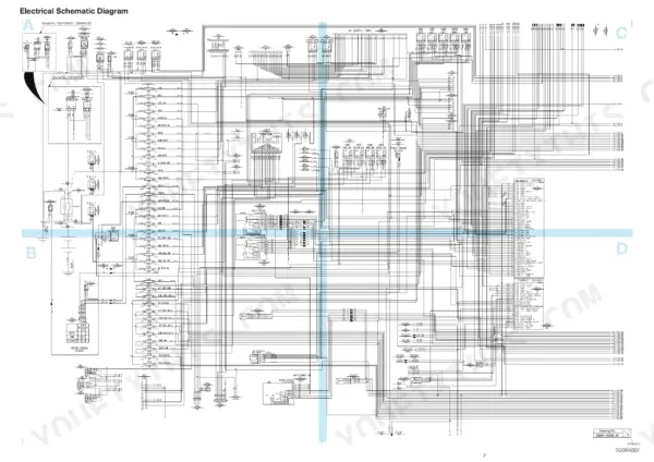
| Electrical Circuit and Wire Harness Diagrams | 63-92 | Wire Colour Codes, Electrical Schematic Diagram with Serial-Number Variants, Wire Harness Diagrams and Connector Layouts |
| Function (Hydraulic Components Operation) | 93-170 | Hydraulic Pump, Gear Pump, HST Pump, Control Valves, Pilot Valves, Proportional and Emergency Shut-Off Solenoid Valves, Selector, Check and Brake Valves, Cylinders, Slew Motor, Swivel Joint |
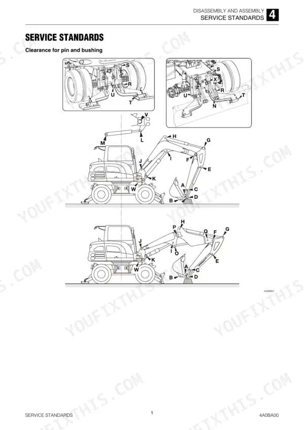
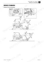
| Drive, Travel, Slew Equipment, Upper Frame and Operating Device | 171-213 | Service Standards, Drive System, Travel System, Slew Equipment, Upper Frame and Operating Device Removal and Installation |
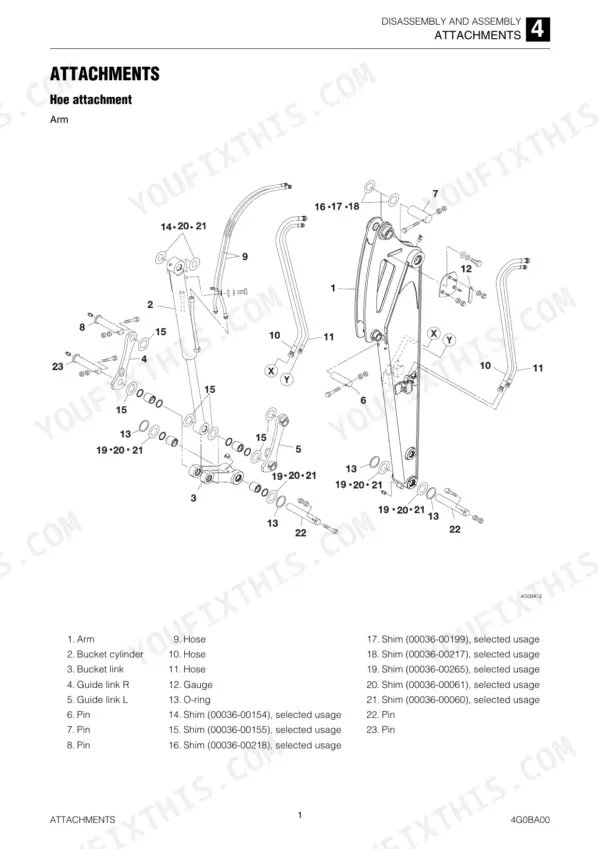
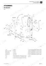
| Attachments | 214-234 | Boom, Arm, Bucket and Blade Attachment Removal, Installation and Pin/Bushing Service |
| Hydraulic Tank and Hydraulic Pump | 235-247 | Hydraulic Tank, Main Piston Pump Disassembly, Inspection and Assembly |
| Gear Pumps (Steering, Pilot Pressure and Slew) | 248-261 | Gear Pump Disassembly, Inspection and Assembly for Steering/Pilot and Slew Circuits |
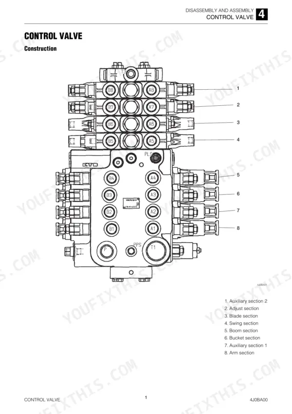
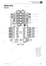
| Control Valves | 262-275 | Main Control Valve and Slew/Pressurization Control Valve Disassembly and Assembly |
| Pilot Valves | 276-294 | Control Lever Pilot Valve, Swing and Blade Pilot Valve Construction, Disassembly and Inspection |
| Solenoid, Selector, Check and Brake Valves | 295-325 | Proportional Control Solenoid Valve, Emergency Shut-Off Valve, Pilot Pressure, Ram/Differential Lock, Swing/Adjust and Forward/Reverse Switching Solenoid Valves, Selector Valve, Check Valve, Brake Valve |
| Hydraulic Cylinders | 326-342 | Boom, Arm, Bucket, Swing and Blade Cylinder Disassembly, Seal Replacement and Assembly |
| Slew Motor and Swivel Joint | 343-371 | Slew Motor and Reduction Gear Overhaul, Swivel Joint Disassembly and Assembly |
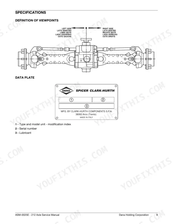
| Front Axle (Dana Spicer Axle 212 Service Manual) | 372-548 | Front Axle Part Number 19160-40400, Bound-In Dana Service Manual Axle 212 Asm-0025E: Planetary Wheel Ends, Differential and Limited Slip, Brakes, Steering Cylinder |
| Rear Axle (Dana Spicer Axle 112 Service Manual) | 549-819 | Rear Axle Part Number 19160-40800, Bound-In Dana Service Manual Axle 112 Asm-0004E: Planetary Wheel Ends, Differential, Brakes, Gearbox |
| Steering Valve (Danfoss OSPB/OSPC/OSPF Steering Unit) | 820-852 | Bound-In Danfoss Hydrostatic Steering Unit OSPB, OSPC and OSPF Service Manual: Exploded Views, Tools, Dismantling, Pressure Relief Valve, Assembling |
| Travel Motor (Sauer-Danfoss Series 51 Bent Axis Motor) | 853-1058 | Bound-In Sauer-Danfoss Series 51 and 51-1 Bent Axis Motor Repair Instructions, Service Manual and Technical Information: Displacement Limiters, Controls |
| HST Pump (Sauer-Danfoss H1 Axial Piston Pump) | 1059-1271 | Bound-In Sauer-Danfoss H1 Closed Circuit Axial Piston Pump Service Manual, Repair Instructions and Technical Information: EDC Control, Charge Pump, Displacement Limiter |
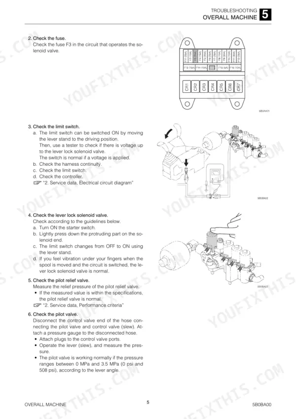
| Troubleshooting | 1272-1323 | Overall Machine, Traveling, Slewing, Boom, Arm, Bucket, Blade, Outrigger, Ram Lock, Auxiliary Hydraulics, Pumps, Valves, Cylinders and Slew Motor Fault Tables |
| Maintenance Software (Main and Travel ECU) | 1324-1381 | Maintenance Software and Maintenance Cable: Controller Input/Output Monitor, Error Codes, Machine Settings; Travel ECU Maintenance Software |
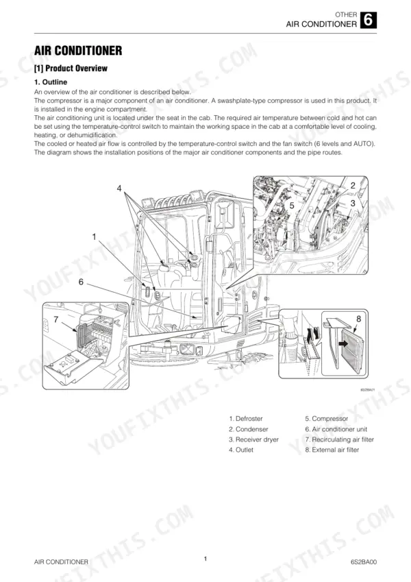
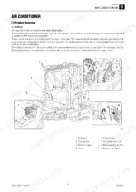
| Air Conditioner and Lever Pattern Switching | 1382-1442 | Air Conditioner Product Overview, Swashplate Compressor, Troubleshooting; Lever Switch Pattern Switching Method |
| Vehicle Error Codes | 1443-1447 | Error Codes for TB295W Vehicles: Code, Malfunction, Detection Port, Trigger Criteria, Operation Limits, Buzzer and Warning Lamp |
Quick Reference Specifications
| Specification | Value | Page |
|---|---|---|
| Engine | ISUZU 4JJ1 | p. 22 |
| Total displacement | 2999 mL (183 cu. in.) | p. 22 |
| Rated horse power | 77 kW (103.3 hp) / 2400 min-1 | p. 21 |
| Maximum torque | 385 N·m (284 ft.-lb.) / 1600 min-1 | p. 22 |
| Engine oil pan | Upper limit 15 L (15.8 US qt.), lower limit 11 L (11.6 US qt.) | p. 29 |
| Hydraulic oil | Total 175 L (46.2 US gal.), tank 82 L (21.7 US gal.) | p. 29 |
| Engine cooling system | 12 L (12.7 US qt) | p. 29 |
| Boom relief pressure | 27.5 MPa (3989 psi) | p. 31 |
| Travel relief pressure | 35.0 MPa (5076 psi) | p. 31 |
| Slew relief pressure | 24.0 MPa (3481 psi) | p. 31 |
| Pilot pressure | 3.5 MPa (508 psi) | p. 31 |
| Engine speed, High (Power mode) | 2000 +20/-20 min-1 | p. 31 |
Takeuchi TB295W Common Problems This Manual Covers
CAN communication code such as 502 with the warning lamp on
Look up 502 in the Vehicle Error Codes table. It gives the detection port and trigger criteria, so you know which module lost contact. Then use the wire harness diagrams and connector layouts to trace that harness. Check the serial-number variant of the schematic before you trust a wire colour.
Manual Section: Vehicle Error Codes; Electrical Circuit and Wire Harness Diagrams p. 1446Overheat alarm (code 3500) under load
Code 3500 sets at 105°C (221°F) water temperature or higher. Confirm the cooling system holds its 12 L (12.7 US qt) and check the radiator for restriction before you suspect the sender. The Overall Machine fault tables in Troubleshooting take you through the checks in order.
Manual Section: Vehicle Error Codes; Troubleshooting; Service Data p. 1446All systems work, but the machine is short on power
This exact symptom appears in the Overall Machine troubleshooting table. First confirm high idle is 2000 +20/-20 min-1 in power mode. Then check pilot pressure at P4 for 3.5 MPa (508 psi), and put a gauge on the relief valves using the pressure measuring method in Service Data.
Manual Section: Troubleshooting; Service Data: Standard Values and Pressure Measuring Methods p. 1275Travel is weak or will not engage
Check charge pressure first. It should be 2.4 MPa (348 psi). Travel relief should be 35.0 MPa (5076 psi) front and rear. If those readings are low, the bound-in Sauer-Danfoss H1 HST pump manual covers the charge pump, EDC control and displacement limiter. The Series 51 manual covers the bent axis travel motor.
Manual Section: HST Pump (Sauer-Danfoss H1); Travel Motor (Sauer-Danfoss Series 51); Troubleshooting: Traveling p. 31Frequently Asked Questions
How do I read error codes on a Takeuchi TB295W?
You read codes with Takeuchi's maintenance software and maintenance cable. The Maintenance Software chapter covers both the main ECU and the travel ECU. It shows controller inputs and outputs, error codes and machine settings. Codes also show on the cluster gauge or LCD screen. The Vehicle Error Codes table lists each code's trigger criteria and operation limits, and the repair order runs from mechanical checks to the detection ports, the lines and then parts. p. 1443
What do error codes 3401 and 3500 mean on the TB295W?
Code 3401 means engine oil pressure has dropped below 100 kPa. Code 3500 means an overheat, with water temperature at 105°C (221°F) or higher. For each code, the Vehicle Error Codes table gives the detection port, what the machine limits, and whether the buzzer and warning lamp come on. Code 3600 is a clogged air cleaner, which is a cheap fix. p. 1446
Where are the TB295W torque specs, and does it cover the boom pins?
The Service Data chapter has bolt and hose torque tables. For JIS strength category 10.9 bolts, coarse M10 × 1.5 is 47.1 ± 2.4 N·m (34.7 ± 1.7 ft-lb). M12 × 1.75 is 83.4 ± 4.1 N·m (61.5 ± 3.0 ft-lb). Boom, arm, bucket and blade pin removal, installation and bushing work are in the Attachments chapter. p. 48
What are the TB295W relief pressure settings and how do I check them?
Boom head relief is 27.5 MPa (3989 psi). Front and rear travel relief is 35.0 MPa (5076 psi) and slew relief is 24.0 MPa (3481 psi). Steering is 14.0 MPa (2031 psi). Take readings at 2000 min-1 in power mode, with the oil at 50°C to 60°C. Pilot pressure is 3.5 MPa (508 psi), read at port P4, size G1/4. p. 31
Does it cover the Isuzu 4JJ1 engine?
It gives you specs and service data but no overhaul procedures. You get displacement of 2999 mL and max torque of 385 N·m (284 ft.-lb.) at 1600 min-1. Engine speeds are listed, including 1050 +70/-20 for manual DPF regeneration. The oil pan takes 15 L (15.8 US qt.) at the upper limit, using SAE 10W-40 or 15W-40, API CJ-4. For a teardown you need the Isuzu manual. p. 22
Reviews
There are no reviews yet.