
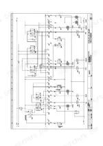
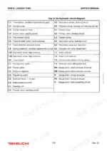
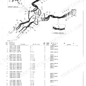
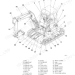
Hydraulics fill more of this 308-page Takeuchi TW80 service manual PDF (OEM ID 8015739) than any other system on the wheel loader: travel pump, load and charge pumps, travel motor and loading circuit control block, with the articulated pendulum joint, lift arms, diesel engine, axles, brakes and cab covered too. A hydraulic circuit diagram maps the travel and charge pumps, control valve, pressure relief valve and travel motor, while an appendix of electrical circuit diagrams backs up the fuse and relay overviews. Each major chapter pairs faults with causes and fixes, and the hydraulic setting instructions show you where to fit gauges before you adjust anything. Check for 1.4 mm play on the rear axle brake laminated disks, then torque the big M52x2.0 hose fitting to 600 to 640 Nm. Made-up hose torques end in blown lines. Bookmarks take you straight to each chapter of this text-searchable PDF, so your TW80 is lifting and loading again sooner.
What's Inside This Takeuchi TW80 Manual
| System | Pages | Key Topics |
|---|---|---|
| Preface | 3-4 | Technical Standards, Safety Regulations, Operating Instructions, Machine Components |
| Introduction | 9-22 | User Information on the Service Manual, Breakdown of Assembly Groups and Chapter Overview, Technical Description of the Wheel Loader |
| Front and Rear Carriage | 23-46 | Front Carriage, Repairing the Front Carriage |
| Hoisting Gear | 47-58 | Operating Faults and Solutions, Maintenance Work (Greasing the Hoisting Gear) |
| Hydraulic System | 59-176 | Breakdown of Assembly Groups, Technical Data, Faults, Causes and Corrective Measures, Setting Instructions |
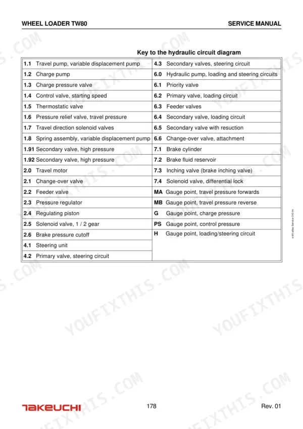
| Appendix to Chapter 3: Hydraulic Circuit Diagram | 177-180 | Travel Pump, Charge Pump, Control Valve, Pressure Relief Valve, Thermostatic Valve, Travel Motor |
| Electrical System | 181-198 | Overview of Fuses and Relays (Lighting), Operating Faults, Maintenance Procedures, Setting Instructions |
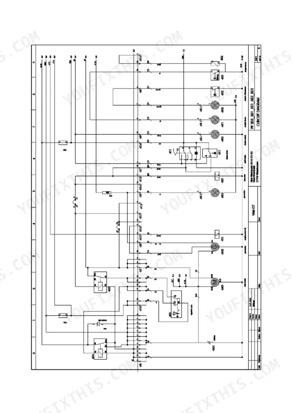
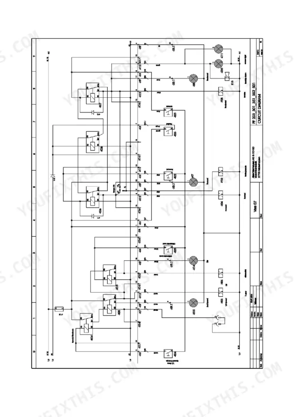
| Appendix to Chapter 4: Electrical System Circuit Diagrams | 199-214 | - |
| Diesel Engine | 215-248 | Breakdown of Assembly Groups, Technical Data (Fuel, Engine Oil, Engine Electrical System), Faults, Causes, Solutions (Faults, Causes and Solutions Related to the Diesel Engine) |
| Axles and Brakes | 249-282 | Operating Faults and Solutions, Maintenance Work, Axles (Lubricants and Filling Quantities, Checking the Axle Oil Levels, Checking and Changing the Brake Fluid) |
| Operator's Cab | 283-302 | Breakdown of Assembly Groups, Operating Faults and Solutions, Maintenance Work (Cleaning Work, Monthly Maintenance, Checking Fill Levels) |
| Table of Topics | 303-308 | Articulated Pendulum Joint, Hydraulic Cylinders, Steering Unit, Diesel Engine, Brake Fluid, Accelerator Cable |
Quick Reference Specifications
| Specification | Value | Page |
|---|---|---|
| Self-locking screws (2) torque | 120 Nm | p. 34 |
| Hexagon socket screws (4) torque | 50 Nm | p. 34 |
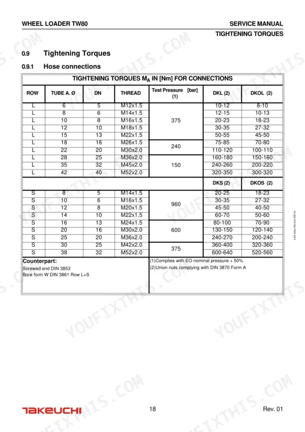
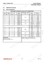
| Tightening torque for hose connection (Tube A. Ø 6, Thread M12x1.5, DKL) | 10-12 Nm | p. 18 |
| Tightening torque for hose connection (Tube A. Ø 38, Thread M52x2.0, DKS) | 600-640 Nm | p. 18 |
| Play of the brake laminated disks | 1.4 mm | p. 274 |
| Spacer ring S4 thickness | 1.5 mm | p. 274 |
| Articulated pendulum joint angular movement | ±12° | p. 12 |
| Steering wheel full lock (jack-knifing) | 40° | p. 12 |
| Diesel engine nominal speed, max. | 2300 min-1 | p. 216 |
| Engine oil volume with filter | 10.5 liter | p. 216 |
| Fan belt pretension value | 450 N ± 20% | p. 225 |
| Fan belt post-tension value | 350 N ± 20% | p. 225 |
Takeuchi TW80 Common Problems This Manual Covers
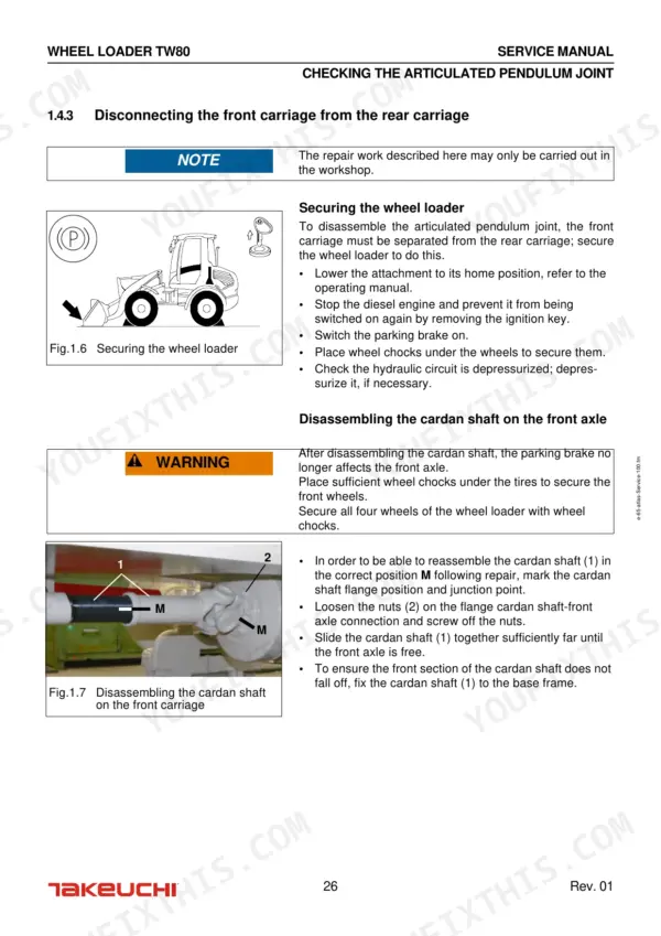
Takeuchi TW80 articulated pendulum joint making noises when turning with jerky angular movements
Check the articulated pendulum joint for noise and jerky travel by steering slowly from lock to lock. Verify the joint swings through its full ±12° angular movement and the steering reaches 40° full lock, both listed on page 12. Then work the pendulum joint fault table in the Front and Rear Carriage chapter starting on page 23.
Manual Section: Front and Rear Carriage p. 23Hoisting gear on the lift arms developing lateral play, noises and sluggish hydraulic cylinders
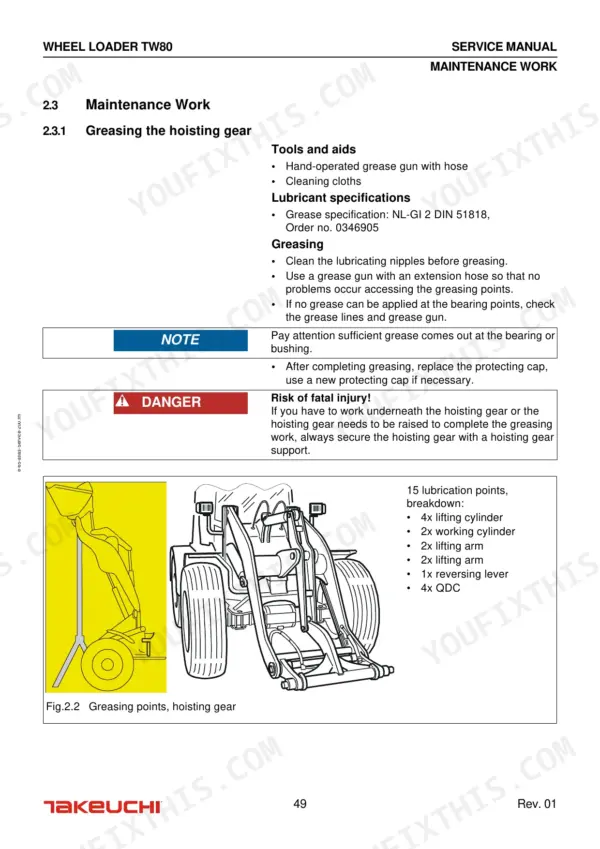
Check the hoisting gear for lateral play and noise by cycling the lift arms and bucket with no load. Grease the hoisting gear following the maintenance schedule on page 49 and the service procedures on page 52. If the hydraulic cylinders stay sluggish after greasing, work through the Hoisting Gear fault table beginning on page 47.
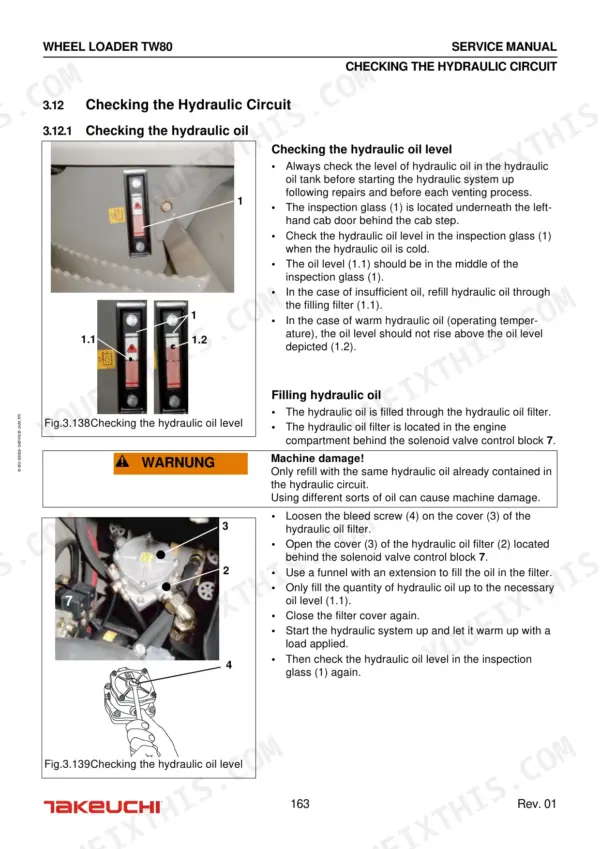
Manual Section: Hoisting Gear p. 47Hydraulic oil running hot with slow cool-down, fan rotation problems and oil leaks
Check fan rotation with the engine running and confirm the hydraulic oil cools down after shutdown. Trace the thermostatic valve on the hydraulic circuit diagram on page 178. Inspect every hose for weeping and torque the hydraulic hose connection pieces to 85 + 5 Nm as listed on page 162.
Manual Section: Hydraulic System p. 59Loading circuit with no pressure, hoisting gear sinking and the bucket tipping automatically
Test loading circuit pressure before touching the cylinders. Trace the control valve and pressure relief valve on the hydraulic circuit diagram on page 178, then check both against the setting instructions in the Hydraulic System chapter starting on page 59. If the hoisting gear still sinks, work through the loading circuit pressure fault table.
Manual Section: Appendix to Chapter 3: Hydraulic Circuit Diagram p. 178Diesel engine overheating while running rough with low power and off-color exhaust
Check fan belt tension first: set pretension to 450 N ± 20% and post-tension to 350 N ± 20% following page 225. Measure the fan propeller gap against 0.2 mm to 0.8 mm on page 239. For rough running, check inlet valve play at 0.3 mm and outlet at 0.5 mm on page 227.
Manual Section: Diesel Engine p. 215Axles making noise with gear oil level rising and brake fluid level problems
Check the axle oil levels and the brake fluid level following the Axles and Brakes maintenance work starting on page 249. Change the brake fluid if it is contaminated. With the axle opened, measure brake laminated disk play against 1.4 mm on page 274, and correct it with the spacer ring S4 thickness listed there.
Manual Section: Axles and Brakes p. 249Frequently Asked Questions
What are the torque specifications for hose connections on the Takeuchi TW80?
The tightening torques for hose connections vary based on the thread size and type. For example, a M12x1.5 thread (DN 5) requires 10-12 Nm for DKL connections and 8-10 Nm for DKOL connections. For larger M52x2.0 threads (DN 40), the torque is 320-350 Nm for DKL and 300-320 Nm for DKOL. p. 18
What is the correct engine oil change interval for the Takeuchi TW80?
The engine oil change interval for the Takeuchi TW80 is every 500 operating hours. The engine oil volume required with the filter is 10.5 liters. p. 216
What is the correct pretension and post-tension value for the fan belt?
The pretension value for the fan belt is 450 N ± 20%. The post-tension value, after the engine has run with a load applied for 15 minutes, is 350 N ± 20%. p. 225
What is the procedure for adjusting the valve play on the diesel engine?
Valve play must be checked after 50 operating hours and then every 1000 operating hours. The inlet valve play should be 0.3 mm and the outlet valve play should be 0.5 mm. p. 227
What is the tightening torque for the main drive pinion screw on the Takeuchi TW80 axle transfer box?
The fastening screw for the main drive pinion on the axle transfer box must be tightened to a torque of 52-58 Nm. p. 262
Will this Takeuchi TW80 Service Manual download right away?
Instant PDF download. You get the full 308-page searchable Service Manual immediately after payment. Open it on your laptop, tablet, or phone right in the shop.
Can I print a copy of this Takeuchi TW80 Service Manual for the shop?
Printing is allowed without restriction. Pull the pages you need for the job and bin them when they get greasy.
Reviews
There are no reviews yet.