
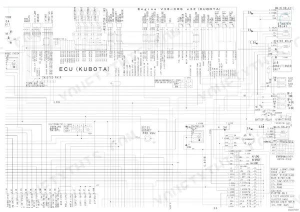
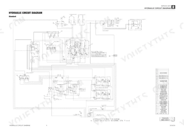
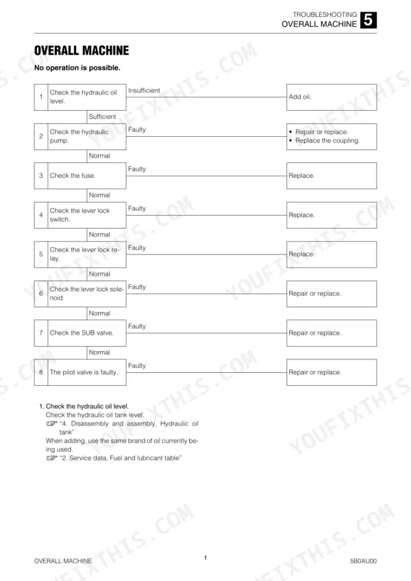
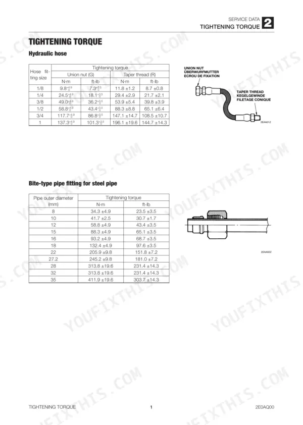
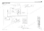
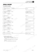
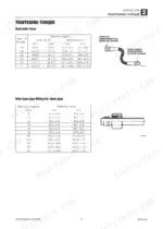
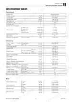
A TL10 that creeps on one track or lets its lift arms drift under load is hard to sort out from memory. The Takeuchi TL10 service manual PDF (OEM ID CU6E005) answers it with 409 pages of factory data on that track loader. Wiring diagrams and hydraulic schematics lead the Service Data section, and the Function chapter traces oil through the standard and high flow control valves. Disassembly and assembly fills close to half the book, from the HST pump and travel motor to cylinders, frame and attachments, while troubleshooting is sorted by overall machine, traveling, lift arm and bucket. Fill track roller A with 0.18 L of oil and the idler with 0.17 L, and run a 1/8 hydraulic hose union nut to 9.8 N·m. Some days it's you, the loader and nobody to ask. Bookmarks and a text layer get you to any section fast, and printed pages can live on your bench and soak up oil.
What's Inside This Takeuchi TL10 Manual
| System | Pages | Key Topics |
|---|---|---|
| Safety | 3-12 | Safety Alert Symbol, Safety Label, Prepare the Work Area, Handling of Hoses |
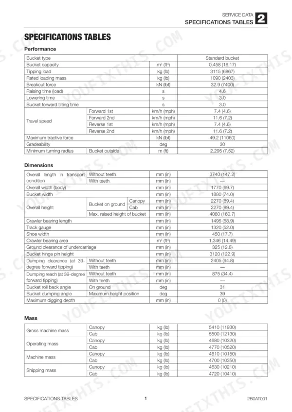
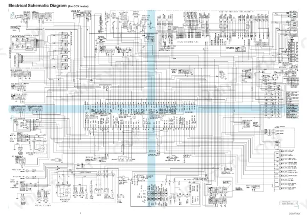
| Service Data | 13-70 | Specifications Tables, Performance Criteria, Electrical Wiring Diagram |
| Function | 71-103 | Control Valve, Control Valve High Flow |
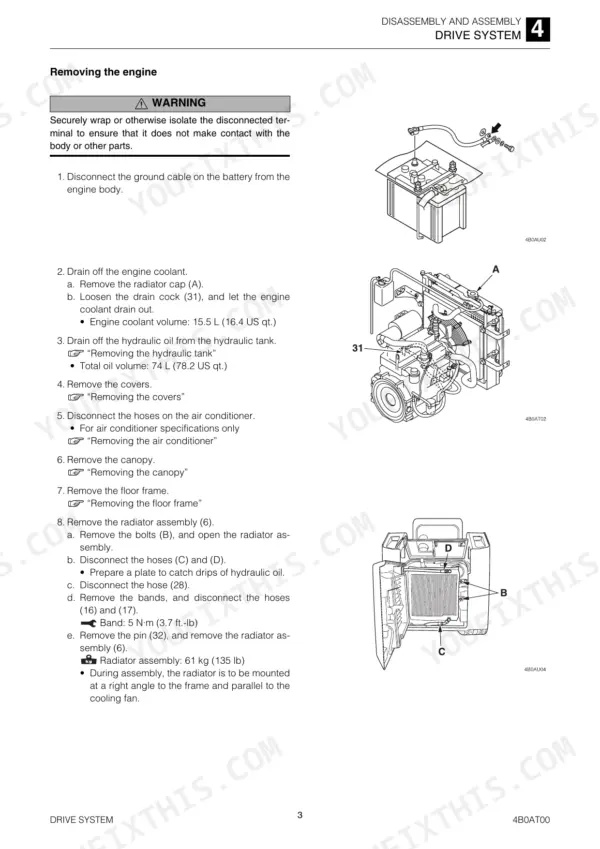
| Disassembly and Assembly | 104-120 | Service Standards, Drive System, Travel System |
| Frame | 121-155 | Operating Device, Attachments, Hydraulic Tank |
| HST Pump and Gear Pumps | 156-218 | HST Pump, Gear Pump, Gear Pump (High Flow), Inspection and Adjustment, Test Operation |
| Control Valve | 219-245 | Control Valve (High-Flow), Sub Valve, Pilot Valve, Proportional Control Solenoid Valve |
| Cylinders | 246-260 | Piston Rod Assembly, Rod Cover, No-Load Operation Test |
| Travel Motor | 261-282 | Reduction Gears, Hydraulic Motor, Use Limit for Parts |
| Troubleshooting | 283-322 | Overall Machine, Traveling, Lift Arm, Bucket |
| Other | 323-409 | Air Conditioner System, Maintenance Software Manual |
Quick Reference Specifications
| Specification | Value | Page |
|---|---|---|
| Track roller A oil capacity | 0.18 L (6.09 fl. oz) | p. 18 |
| Track roller B oil capacity | 0.17 L (5.75 fl. oz) | p. 18 |
| Seal tape overlap | 10 mm (0.39 in) | p. 11 |
| Hydraulic hose union nut (G) 1/8 | 9.8 +4.9 N·m | p. 29 |
| Sprocket standard dimension A | 410 mm (16.1 in.) | p. 105 |
| Sprocket allowable value A | 402 mm (15.8 in.) | p. 105 |
| Check valve torque | 59 N·m (43.5 ft.-lb) | p. 118 |
| Crawler belt weight | 255 kg (562 lb) | p. 118 |
| Travel motor weight | 81 kg (179 lb) | p. 120 |
| Internal leak flow rate | 1 mL/3 min. (0.06 in3/3 min.) or less | p. 260 |
| Engine Rated Horsepower (Gross) | 68.6 kW (92.0 hp) | p. 16 |
| Hydraulic Drive System Set Pressure | 34.5 MPa (5000 psi) | p. 16 |
Takeuchi TL10 Common Problems This Manual Covers
Takeuchi TL10 lift arm and bucket slow or failing to move with insufficient power
Check whether the lift arms and bucket are both slow, or only one circuit is lazy, before you pull a cylinder. Follow the overall machine troubleshooting flow on page 285, which separates no operation from insufficient power. If both functions drag together, test gear pump discharge using the gear pump troubleshooting chart.
Manual Section: Overall Machine Troubleshooting p. 285Machine veers to one side when traveling straight and runs at high operating temperature
Check whether the pull always goes to the same track, then follow the traveling troubleshooting tree starting on page 291 for veering and high operating temperature. Test HST pump neutral position and travel output with the HST pump chart. Inspect the travel motor on the weak side for speed issues and rotational fluctuations before you condemn the pump.
Manual Section: Traveling Troubleshooting p. 291Lift arm cylinder drops spontaneously when the arms are raised and the controls held in neutral
Inspect the lift arm cylinder for external oil leaks first, then work through the lift arm troubleshooting steps on page 298 for spontaneous drop. Check the control valve for spool sliding problems and actuator drop using the control valve chart. Test the cylinder against the cylinder troubleshooting chart before you tear it down on the bench.
Manual Section: Lift Arm Troubleshooting p. 298Track rollers, idler and sprocket worn below allowable dimension when measured during undercarriage inspection
Measure each part against the wear limits on page 105. Sprocket dimension A runs from 410 mm (16.1 in.) standard to 402 mm (15.8 in.) allowable, the idler from 450 mm to 440 mm, and track roller A from 216 mm to 208 mm. Replace anything under the limit and torque the sprocket fixing bolts to 241 N·m (177.8 ft.-lb) per page 120.
Manual Section: Disassembly and Assembly p. 105Auxiliary hydraulics fail to supply prescribed pressure when running a hydraulic attachment
Check the auxiliary hydraulics troubleshooting chart for the prescribed pressure not supplied condition before you blame the attachment. Verify sub valve solenoid operation and look for oil leaks at the sub valve and solenoid valve. Test pilot valve secondary pressure using the pilot valve chart, then work back through each valve until you find the one losing pressure.
Manual Section: Auxiliary Hydraulics TroubleshootingTravel motor leaking oil, fluctuating in rotation, or failing to shift into 2nd-speed travel
Inspect the travel motor for oil leaks, then check 2nd-speed control and parking brake operation using the travel motor troubleshooting chart. Check the traveling troubleshooting flow on page 291 for 2nd-speed travel failure. After any repair, fill the travel reduction gear with 1.6 L (1.7 US qt) of oil, as listed on page 18.
Manual Section: Travel Motor TroubleshootingFrequently Asked Questions
How do I retrieve error codes on a Takeuchi TL10?
To retrieve error codes, you must use the Maintenance Software. Connect the Maintenance Tool (product no. 17301-41810) to the machine's CAN_0 connector and your computer, then open the .PID data file in the PLUS+1 GUIDE Service Tool to view active and logged error codes. p. 398
What are the replacement specifications for the track rollers on a Takeuchi TL10?
For Track roller A, the standard dimension for code A is 216 mm (8.5 in.) with an allowable value of 208 mm (8.2 in.). For Track roller B, the standard dimension for code A is 328 mm (12.9 in.) with an allowable value of 320 mm (12.6 in.). p. 105
What is the tightening torque for the main relief valve on the Takeuchi TL10 control valve?
The main relief valve on the control valve should be tightened to a torque of 58.8 N·m to 68.6 N·m (43.4 ft.-lb to 50.6 ft.-lb). p. 220
What is the hydraulic oil tank capacity on the Takeuchi TL10?
The total amount of hydraulic oil in the system is 74 L (19.6 US gal), while the tank capacity itself is 48 L (12.7 US gal). p. 18
What is the tightening torque for the cap screws on the gear pump of the Takeuchi TL10?
The cap screws on the gear pump should be tightened to a torque of 88.2 N·m to 93.1 N·m (65.1 ft.-lb to 68.7 ft.-lb). p. 206
How is this Takeuchi TL10 Service Manual delivered?
Instant PDF download. You get the full 409-page searchable Service Manual immediately after payment. Open it on your laptop, tablet, or phone right in the shop.
Is printing allowed for this Takeuchi TL10 Service Manual?
Yes. Print individual pages or full chapters for your own shop use, on letter or A4 paper.
Reviews
There are no reviews yet.