
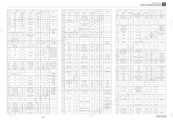
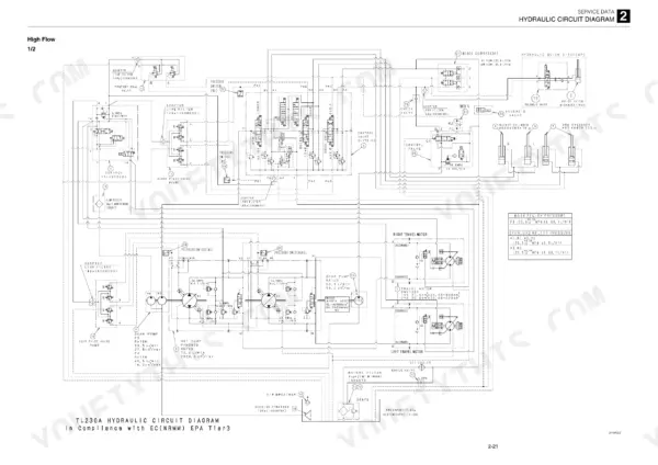
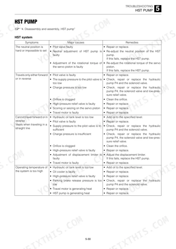
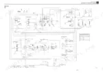
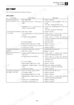
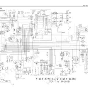
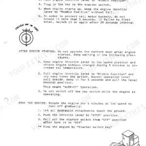
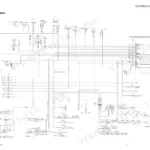
Chasing a slow lift arm or rebuilding a travel motor on a Takeuchi TL230 track loader goes faster with 294 pages of factory data beside you, which is what this Takeuchi TL230 service manual PDF (OEM ID CU5E002) puts on your bench. Hydraulic circuit and electrical wiring diagrams, plus the wire harness layout, lead the service data chapter. Troubleshooting is the biggest single section, tracing symptoms such as a lift arm that drifts down, a machine that veers to one side or dead auxiliary proportional control back to the HST pump, valve or travel motor at fault. Condemn track roller A once it wears from 200 mm to its 194 mm limit, and torque the relief valve on the High flow control valve to 65.0 ±6.5 N·m. A guess costs a seal kit and a second teardown. Bookmarks jump to every chapter and the text layer searches cleanly, so your TL230 is loading trucks again sooner.
What's Inside This Takeuchi TL230 Manual
| System | Pages | Key Topics |
|---|---|---|
| Safety | 3-12 | Safety Alert Symbol, Safety Precautions, Cautions When Working |
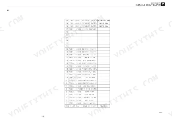
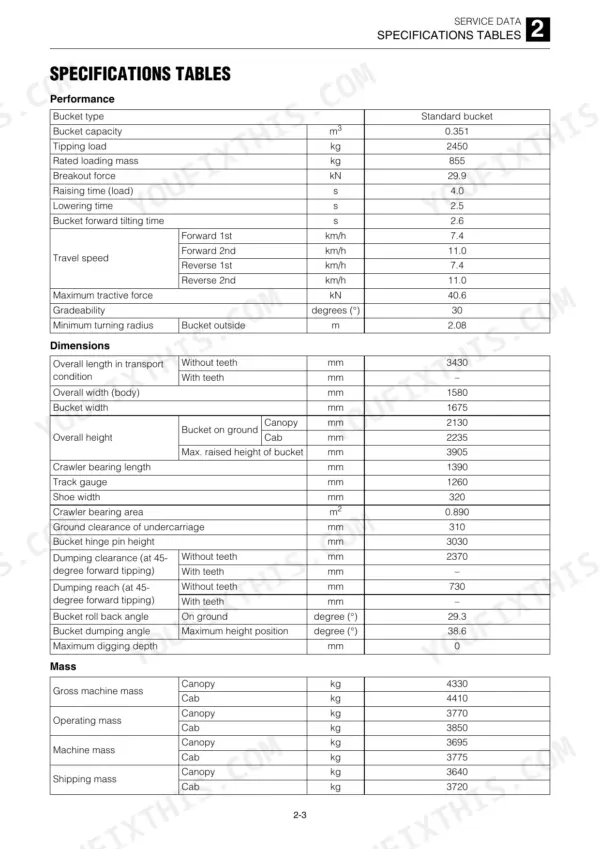
| Service Data | 13-48 | Dimensional Drawing, Specifications Tables, Lubricant and Fuel Chart, Performance Criteria, Tightening Torque, Hydraulic Circuit Diagram, Electrical Wiring Diagram |
| Function | 49-94 | HST Pump, Gear Pump, Control Valve, SUB Valve, Pilot Valve, Proportional Control Solenoid Valve, Cylinders, Travel Motor, Charge Relief Valve, Load Check Valve, Parking Brake, Air Conditioner System |
| Service Standards | 96-97 | Track Roller a, Track Roller B, Drive Sproket, Idler, Pin and Bushing Clearance |
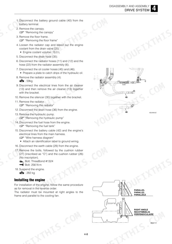
| Drive System | 98-113 | Engine Removal, Hydraulic Pump Removal, HST Pump Air Bleeding, Throttle Lever Adjustment |
| Travel System | 114-116 | Crawler Belt Removal, Track Roller Removal, Idler Removal, Travel Motor Removal |
| Frame | 117-121 | Canopy Tilting, Lift Arm Stopper, Floor Frame Removal, Cover Removal, Canopy/Cab Removal |
| Control System | 122-123 | Hydraulic Pilot Unit, Lever Stand Removal, Lever Stand Installation |
| Attachments | 124-130 | Quick-Hitch Removal, Lift Arm Removal, Bucket Stopper Adjustment, Arm Stopper Adjustment |
| Hydraulic Tank | 131-132 | Hydraulic Tank Removal, Hydraulic Oil Filling, Air Bleeding |
| HST Pump | 133-156 | Hydraulic Pump, Charge Check Valve, High-Pressure Relief Valve, Charge Relief Valve, Flushing Valve |
| Gear Pump | 157-166 | Construction, Disassembly, Inspection and Adjustment, Test Operation, Measuring the Discharge Volume, Gear Pump (High Flow) |
| Control Valve | 167-172 | Operation, Main Relief Valve, Port Relief Valve, Load Check Valve, Flow Ratio Adjuster Valve |
| Control Valve (High Flow) | 173-176 | Disassembly and Assembly, Main Relief Valve, Port Relief Valve, Spool, Inspection and Adjustment |
| Sub Valve | 177-181 | Operation, Disassembly, Inspection and Adjustment |
| Pilot Valve | 182-188 | Operation, Disassembly, Assembly, Inspection and Adjustment |
| Proportional Control Solenoid Valve | 189-190 | Construction, Disassembly, Checking the Parts, Coil Assembly |
| Cylinders | 191-203 | Arm Cylinder, Bucket Cylinder, Piston Rod Assembly, Rod Cover, Clevis, Cylinder Assembly |
| Travel Motor | 204-224 | Hydraulic Motor, Reduction Gears, Floating Seal, Brake Piston, Cylinder Block |
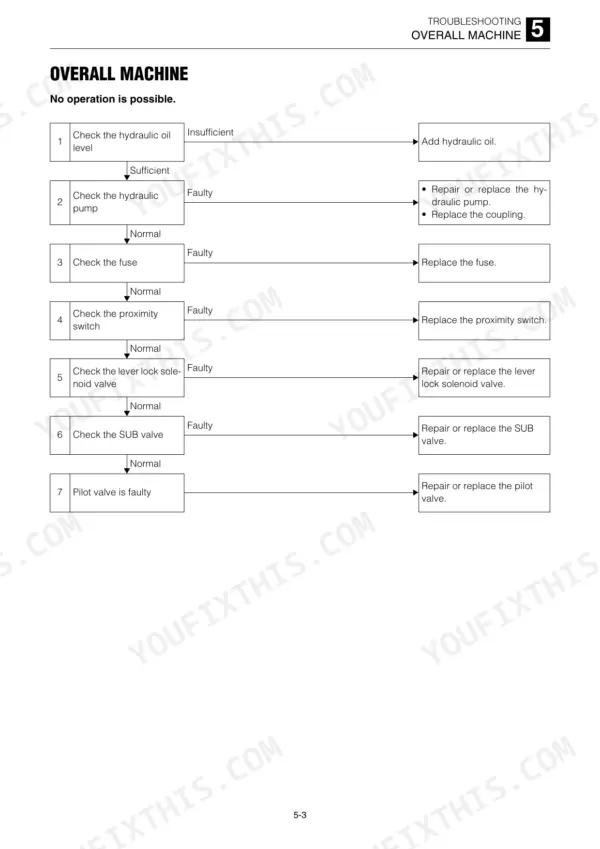
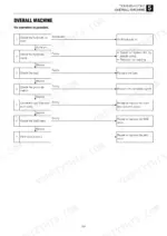
| Troubleshooting | 225-292 | Overall Machine (No Operation Is Possible., All Systems Working, But Insufficient Power., Lift Arm and Bucket Fail to Move or Are Too Slow.) |
| Cluster Gauge | 293-294 | LCD Details, Hour Meter, Battery Voltage, Error Codes, Water Temperature Meter, Fuel Meter |
Quick Reference Specifications
| Specification | Value | Page |
|---|---|---|
| Relief Valve Torque | 65.0 ±6.5 N·m | p. 174 |
| Track roller A standard dimension | 200 mm | p. 96 |
| Track roller A allowable value | 194 mm | p. 96 |
| Drive sproket standard dimension | 414 mm | p. 96 |
| Drive sproket allowable value | 406 mm | p. 96 |
| Idler weight | 35 kg | p. 115 |
| Track adjuster weight | 25 kg | p. 115 |
| Travel motor bolt torque | 241 N·m | p. 116 |
| Travel motor weight | 84 kg | p. 116 |
| Change of pressure per turn | 9 MPa | p. 176 |
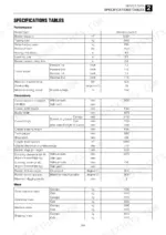
| Engine Oil Pan Capacity | 11.2 L | p. 18 |
| Hydraulic Oil Tank Capacity | 38.7 L | p. 18 |
Takeuchi TL230 Common Problems This Manual Covers
Takeuchi TL230 track loader lift arm and bucket fail to move or respond too slowly
Check hydraulic oil level first; the tank holds 38.7 L per page 18. Then measure gear pump discharge volume following page 157 and listen for pump noise. If flow is good, inspect the control valve main relief valve and load check valve on page 167, and work through the overall machine flow.
Manual Section: Overall MachineLift arm cylinder drops spontaneously when the loaded lift arms are held raised
Test the arm cylinder for internal leakage before pulling the control valve; per page 202 the limit is 1 mL/3 min or less. If the cylinder passes, inspect the load check valve and port relief valve following page 167. Rebuild the piston rod assembly following page 191 if leakage exceeds the limit.
Manual Section: Cylinders p. 202HST pump forward or reverse travel fails to respond with hydraulic oil running high temperature
Check hydraulic oil level against the 38.7 L tank capacity on page 18, then bleed air from the HST pump. Inspect the charge check valve, charge relief valve, high-pressure relief valve and flushing valve following page 133. Work the HST pump neutral, forward/reverse and high temperature checks before condemning the pump.
Manual Section: HST PumpTrack loader veers steadily to one side when traveling straight forward or in reverse
Check travel reduction gear oil against the 1.0 L capacity on page 18. Inspect the travel motor brake piston, cylinder block, reduction gears and floating seal following page 204. On reassembly, torque the ring nut to 200 ± 100 N·m and confirm housing rotational torque of 4.7 to 7.8 N·m per page 215.
Manual Section: Travel Motor p. 204Track rollers, idlers and drive sprocket worn down below the allowable service dimension
Measure track roller A against 194 mm allowable (200 mm standard) and roller B against 320 mm (328 mm standard) per page 96. Replace the drive sprocket below 406 mm (414 mm standard). Torque roller A bolts to 241 N·m and roller B bolts to 156 N·m on page 115, and sprocket bolts to 241 N·m.
Manual Section: Service Standards p. 96Auxiliary hydraulics proportional control fails to respond or solenoid valve leaks oil
Inspect the proportional control solenoid valve for correct operation and external oil leaks following page 189. Disassemble and clean the valve, then reassemble and adjust it using the inspection and adjustment steps in that section. Retest the auxiliary hydraulics under load before you replace the valve.
Manual Section: Proportional Control Solenoid Valve p. 189Frequently Asked Questions
What do the error codes 01, 02, 03, 04, 06, 09, 11, 12, 13, 14, 15, 16, and 17 mean on the Takeuchi TL230?
The error codes indicate specific machine malfunctions: 01 (short-time key switch operations), 02 (low engine oil pressure), 03 (charge alternator malfunction), 04 (engine overheat >120°C), 06 (air cleaner clogged), 09 (emergency release), 11 (excess glow plug ignition time), 12 (battery voltage >24V), 13 (battery voltage <7V), 14 (emergency release signal switch), 15 (real-time lock error), 16 (oil pressure sensor malfunction), and 17 (charger output signal). p. 293
What are the replacement specifications for bottom rollers on the Takeuchi TL230?
For track roller B, the standard dimension for code A is 328 mm, with an allowable wear limit down to 320 mm. For code B, the standard dimension is 40 mm. p. 96
What is the procedure for bleeding air from the HST pump?
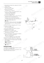
Before installing the HST pump, fill the servo control chambers with hydraulic oil through the pressure detection ports (M4, M5, M14, M15). After installation, fill the pilot hoses (X1, X11) with oil, start the engine at idling speed for five minutes, and bleed the main and pilot circuits by slowly operating the pilot valve. p. 105
What is the tightening torque for the main relief valve on the control valve of the Takeuchi TL230?
The tightening torque for the main relief valve on the control valve is 58.8 to 68.6 N·m. p. 168
What is the hydraulic oil tank and engine cooling system capacity on the Takeuchi TL230?
The hydraulic oil tank has a total capacity of 58 L, with a tank capacity of 38.7 L. The engine cooling system has a capacity of 13.0 L. p. 18
How quickly can I access this Takeuchi TL230 manual after buying?
A 294-page Service Manual in searchable PDF format, available the moment you complete checkout. View on computer, tablet, or phone, with no shipping wait.
Am I free to print this Takeuchi TL230 Service Manual?
Yes. It prints from any PDF reader, so run off the pages you need for your own repair work.
Reviews
There are no reviews yet.