
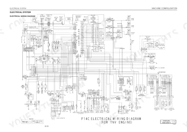
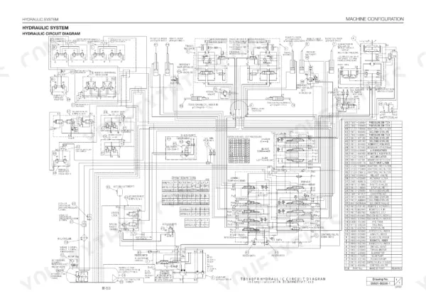
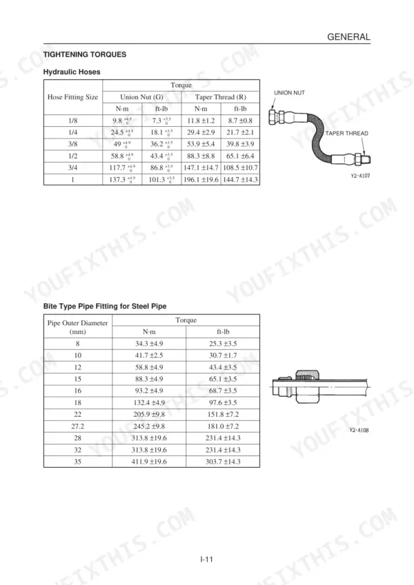
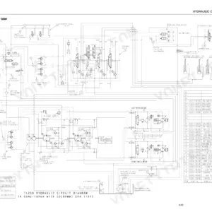
The Takeuchi TB180FR service manual PDF breaks the hydraulic excavator down system by system across 755 pages, published under OEM ID CL5E002. Hydraulic units take up about a quarter of the book: pump, gear pump, control valve, pilot valve, solenoid valves, cylinders and travel motor, each taken through removal, disassembly and reassembly, backed by wiring diagrams for the electrical system and hydraulic schematics showing circuit routing. Troubleshooting runs by function (travel, slewing, boom, arm, bucket, dozer blade, auxiliary hydraulics), and the Yanmar TNV engine section fills nearly the back half, from fuel injection pump to turbocharger. Set steel track tension to 260-280 mm, and torque a 3/8 taper-thread hose fitting to 53.9 N·m (39.8 ft-lb). Sometimes it's just you, the machine, and nobody to call. Your copy is text-searchable and bookmarked by section, so the right page is a click away while you get the TB180FR digging again.
What's Inside This Takeuchi TB180FR Manual
| System | Pages | Key Topics |
|---|---|---|
| Safety Precautions | 3-8 | Safety Alert Symbol, Protective Equipment, Fire Extinguisher, Anti-Explosive Lighting, Battery Hazards, Waste Disposal |
| Cautions During Disassembly and Assembly | 9 | |
| Cautions During Removal and Installation of the Hydraulic Units | 9 | |
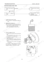
| Cautions During Removal and Installation of Piping | 10 | |
| Handling of Seals | 10 | |
| General Safety and Maintenance | 11-18 | Safety Symbols, Fire Extinguisher, Battery Hazards, Hydraulic Fluid Pressure, Tightening Torques, Bolt and Nut Specifications |
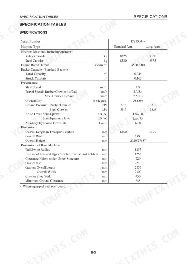
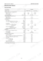
| Specifications | 19-46 | Machine Dimensions, Operating Range, Machine Mass, Recommended Lubricants, Servicing Standards, Performance Inspection Methods |
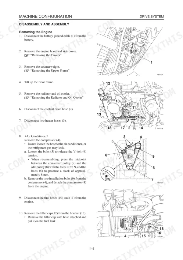
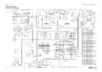
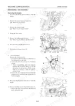
| Machine Configuration | 47-193 | Drive System, Slew System, Travel System, Upper Frame, Control System, Attachments, Hydraulic System, Electrical System |
| Hydraulic Units | 194-387 | Hydraulic Pump, Gear Pump, Control Valve, Pilot Valve, Solenoid Valve, Shut-Off Valves, Cylinders, Travel Motor |
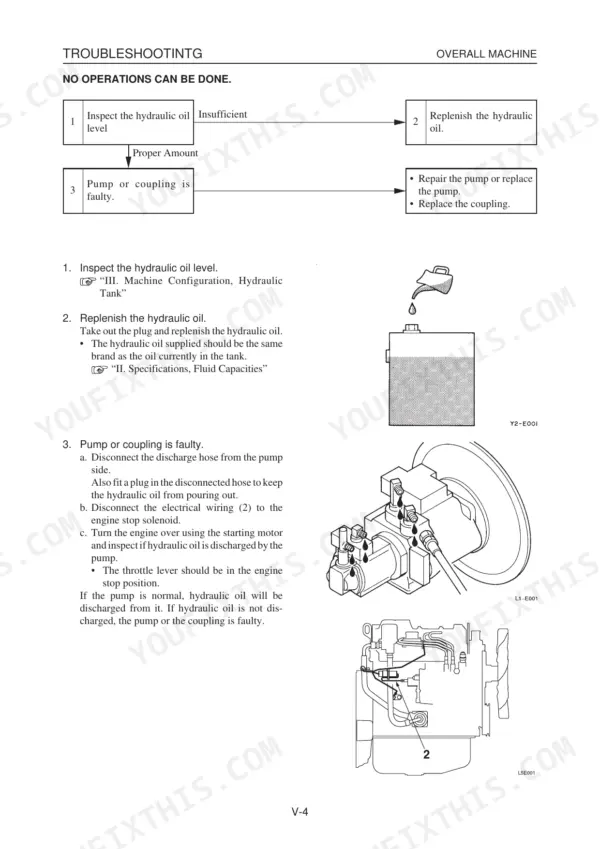
| Troubleshooting | 388-437 | Troubleshooting Procedures, Machine Travel, Slewing, Boom, Arm, Bucket, Dozer Blade, Auxiliary Hydraulics |
| Engine Service Manual | 438-476 | Yanmar TNV Series Engine Specifications, General, Engine Nomenclature, Engine External Views, Exhaust Gas Emission Regulation |
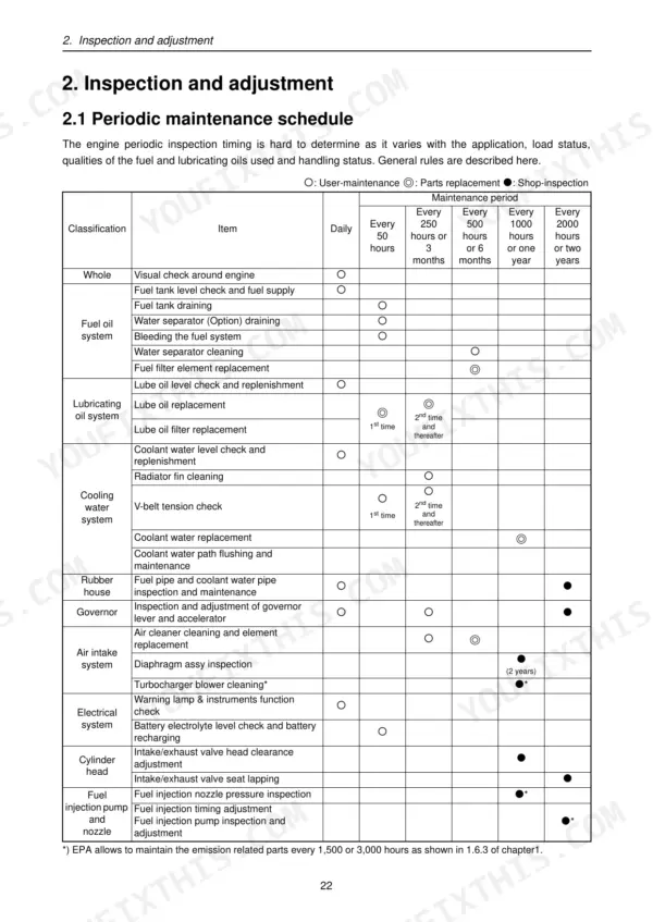
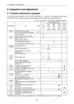
| Inspection and Adjustment | 477-508 | Periodic Maintenance |
| Troubleshooting | 509-514 | Preparation Before Troubleshooting, Quick Reference Table, Compression Pressure |
| Disassembly, Inspection and Reassembly of Engines | 515-563 | Disassembly and Reassembly |
| Lubrication System, Cooling System | 564-571 | Lubrication System, Cooling System, Trochoid Pump, Lube Oil Filter, Cooling Water Pump |
| Fuel Injection Pump / Governor | 572-575 | Fuel Injection Pump, Fuel System Diagram, Cold Start Device |
| Turbocharger | 576-597 | Periodic Inspection Procedure, Waste Gate Valve Adjustment |
| Starting | 598-635 | Starting Motor, Characteristic Test |
| Alternator, Electric Wiring | 636-644 | Alternator, Electric Wiring, Electric Wiring Diagram, Current Limiter |
| Service Standards, Tightening Torques | 645-659 | Service Standards, Engine Tuning, Cylinder Head, Cylinder Block, Tightening Torque for Bolts and Nuts |
| Fuel Injection Equipment | 660-725 | MP Pump, Governor Part, F.O. Feed Pump |
| Engine Trouble Diagnostics Tool and Maintenance Tool | 726-755 | Machines with Standard Engines, TB180FR Maintenance Software |
Quick Reference Specifications
| Specification | Value | Page |
|---|---|---|
| Steel Crawler Tension | 260-280 mm | p. 37 |
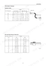
| Hydraulic Hose Taper Thread Torque (1/8 size) | 11.8 ±1.2 N·m (8.7 ±0.8 ft-lb) | p. 15 |
| Hydraulic Hose Taper Thread Torque (1/4 size) | 29.4 ±2.9 N·m (21.7 ±2.1 ft-lb) | p. 15 |
| Rubber crawler weight | 393 kg | p. 69 |
| Steel crawler weight | 482 kg | p. 70 |
| Boom Circuit Relief Valve Pressure | 27.4 +1.8/-0.3 MPa | p. 34 |
| Arm Circuit Relief Valve Pressure | 27.4 +1.8/-0.3 MPa | p. 34 |
| Rubber Crawler Tension | 160-180 mm | p. 37 |
| Drive Sprocket A Basic Dimension | 475.85 mm | p. 31 |
| Carrier roller installation nut torque | 256 N·m | p. 72 |
| Hydraulic tank level capacity | 68 L | p. 104 |
| Boom cylinder pilot valve pressure | 0~3.4 MPa | p. 418 |
Takeuchi TB180FR Common Problems This Manual Covers
Takeuchi TB180FR boom and arm cylinders slow or weak, with low relief pressure and insufficient pump discharge
Check boom and arm circuit relief pressure first; both should read 27.4 MPa (+1.8/-0.3) per page 34. Then measure boom pilot valve pressure against 0 to 3.4 MPa and confirm spool operation pressure reaches 27.5 MPa, as shown on page 418. Don't condemn the pump until both readings are confirmed.
Manual Section: Hydraulic System Troubleshooting p. 34Hydraulic hose union nuts and taper thread fittings leaking oil at the connection
Torque the fitting to spec instead of going by feel. Taper thread fittings take 29.4 ±2.9 N·m for 1/4, 53.9 ±5.4 N·m for 3/8 and 88.3 ±8.8 N·m for 1/2, all listed on page 15. Inspect O-ring grooves for burrs and make sure the O-ring is not twisted, following page 10.
Manual Section: General Safety and Maintenance p. 15Hydraulic oil getting abnormally hot after hours of digging, pump getting noisy
Check the oil level at the hydraulic tank first; tank level capacity is 68 L per page 104. Then verify relief pressures against page 34: boom and arm at 27.4 MPa, slew at 22.1 MPa. After that, work through the abnormal heat and noise steps in the hydraulic system troubleshooting section.
Manual Section: Hydraulic System Troubleshooting p. 104Travel motor slow or stuck in one speed, 2-speed travel control not shifting
Check the 2-speed control first, then test the counterbalance valve before condemning the travel motor itself. Inspect the motor for external oil leaks while you are under there. Work through the Travel Motor Troubleshooting steps for motor movement, speed and counterbalance valve faults before swapping any parts.
Manual Section: Travel Motor TroubleshootingSlew motor slow to start or making abnormal noise, upper frame rebounding at stop
Verify slew relief pressure first: the right and left slew circuits should both read 22.1 MPa (+2.2/-0.2) per page 34. If pressure is in spec, inspect the anti-rebound valve and check the motor for oil leaks. Then follow the Slew Motor Troubleshooting steps for start, speed and abnormal noise faults.
Manual Section: Slew Motor Troubleshooting p. 34Rubber crawler running loose on the undercarriage with track tension out of spec
Measure crawler tension against 160 to 180 mm for rubber crawlers or 260 to 280 mm for steel, as listed on page 37. Check tensioning pressure against 2.0 MPa for rubber and 1.0 MPa for steel per page 71. When refitting rollers, torque carrier roller nuts to 256 N·m and track roller bolts to 102 N·m.
Manual Section: Machine Configuration p. 37Frequently Asked Questions
How do I release residual hydraulic pressure on a TB180FR?
To release residual hydraulic pressure, you must gradually loosen the vent plug to relieve tank pressure. Then, move all control levers and pedals in all directions several times to release pressure from the working equipment circuitry. When removing plugs, screws, or disconnecting hoses, stand to the side and loosen slowly to gradually release internal pressure before fully removing them. p. 11
What is the hydraulic relief pressure on a Takeuchi TB180FR?
The main relief valve pressure settings for the TB180FR are 27.5 MPa and 23.5 MPa. The port relief valve pressure settings are 33.3 MPa, 26.9 MPa, and 20.6 MPa. p. 25
How do I check the hydraulic pressure on a TB180FR?
To check the hydraulic pressure, ensure the engine is at rated r.p.m. and the hydraulic oil temperature is between 50-60°C. Mount a pressure gauge on the designated pressure detection port (P1 for boom, P2 for arm), operate the desired hydraulic circuit, and measure the relief pressure. p. 36
What are the replacement specifications for fuel filters on the TB180FR?
The fuel filter should be replaced every 500 hours or 6 months. When replacing, use a filter wrench to remove the old filter, clean the mounting surface, apply a thin layer of fuel oil to the new gasket, and tighten it 3/4 of a turn after it contacts the mounting surface. p. 491
What is the cylinder head bolt tightening torque for the 4TNV98 engine on the Takeuchi TB180FR?
For the 4TNV94L/98 engine, the first step of tightening the cylinder head bolts is 49.0 to 58.8 N·m (5.0 to 6.0 kgf·m), and the second step is 103.1 to 112.9 N·m (10.5 to 11.5 kgf·m). p. 530
Will this Takeuchi TB180FR Service Manual download right away?
This is a 755-page searchable PDF ready for immediate download. Works on any device, so pull it up on your phone while you're under the hood. No shipping, no waiting.
Am I able to print pages from this Takeuchi TB180FR manual?
Yes. Print individual pages or full chapters for your own shop use, on letter or A4 paper.
Reviews
There are no reviews yet.