
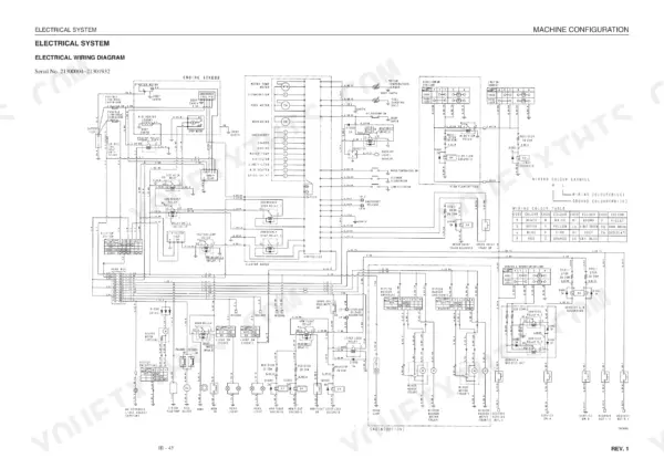
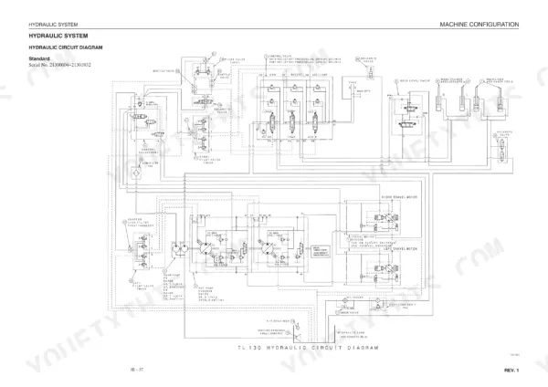
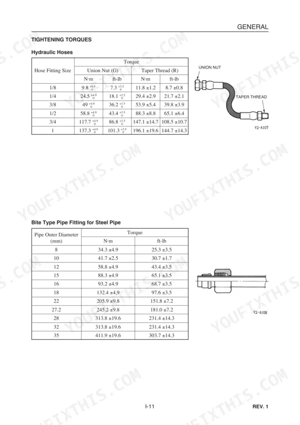
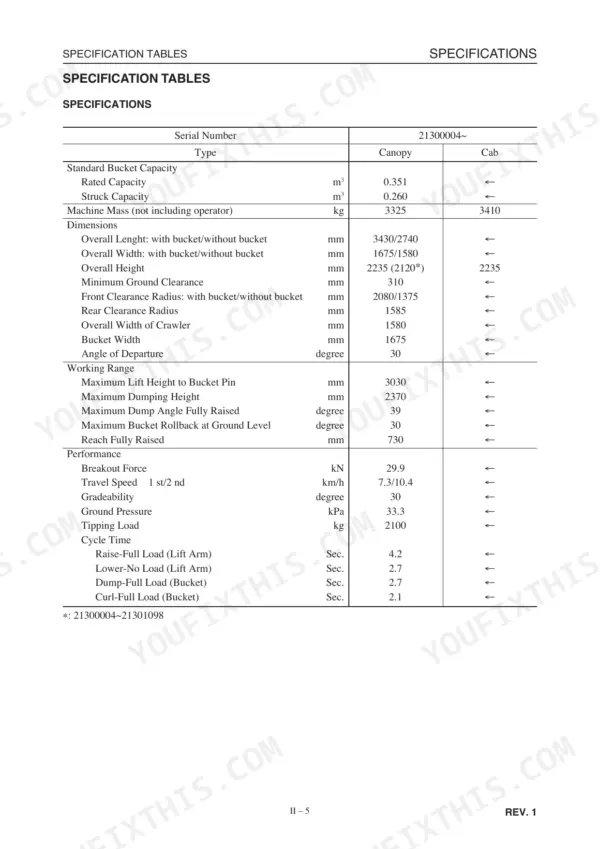
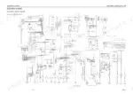
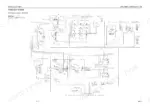
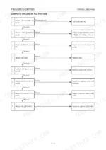
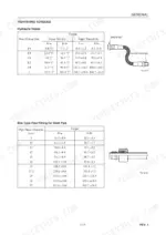
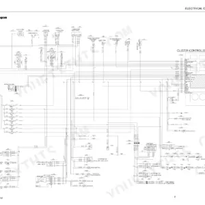
Landed on this page hunting real data for your Takeuchi TL130 Crawler Loader? This 711-page Takeuchi TL130 Workshop Manual (OEM #CT8E002) breaks down the crawler chassis and the full TNV engine lineup, from the 3TNV82A up through the 4TNV94L-98-106(T). Inside you get complete wiring diagrams for chasing electrical faults, hydraulic schematics covering the HST pump, gear pump, and control valve circuits, and a dedicated troubleshooting section for when the lift arms go soft or travel power drops off. Exploded views and torque tables back up every rebuild step. Set the 1/2-inch hydraulic union nut to 58.8 N-m, and follow the exact bleed sequence for the cylinders before you fire the machine back up. No more chasing hydraulic gremlins with a pressure gauge and a guess. Bookmarked by section and searchable by keyword, so you find the spec and get back under the machine.
Complete the set for your TL130
- Parts Catalog: Takeuchi TL130 Parts Manual
What's Inside This Takeuchi TL130 Manual
| System | Pages | Key Topics |
|---|---|---|
| General Information | 9-22 | Safety Precautions, Cautions During Disassembly and Assembly, Standard Maintenance |
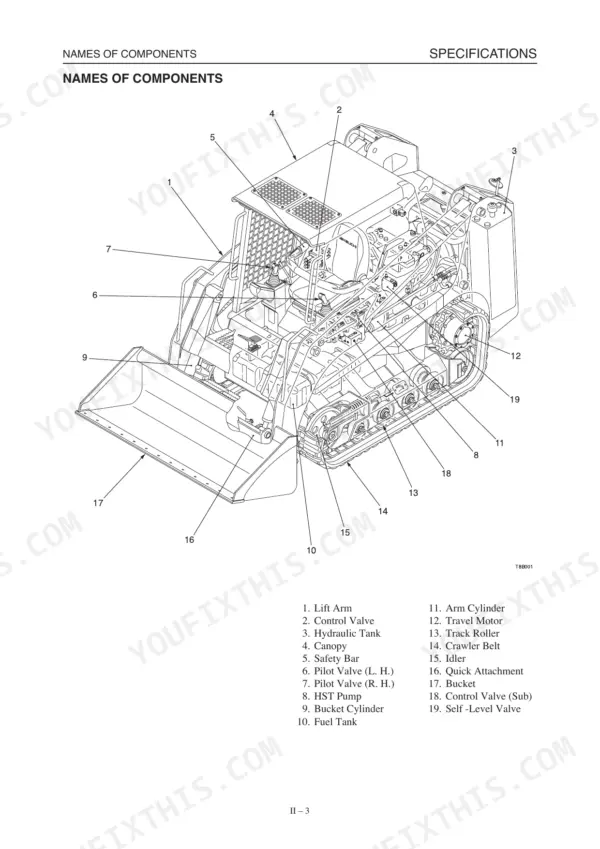
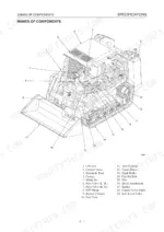
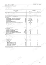
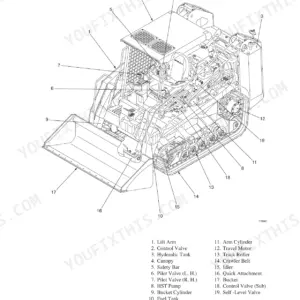
| Specifications | 23-44 | Names of Components, Specification Diagrams, Machine Specifications, Dimensions |
| Machine Configuration | 45-162 | Drive System, Travel System, Frame, Control System, Attachments, Undercarriage |
| Hydraulic Units | 163-282 | HST Pump, Gear Pump, Control Valve, Control Valve (Sub), Cylinders, Swivel Joint |
| Troubleshooting | 283-310 | System Diagnostics, Fault Isolation, Hydraulic Circuit Checks, Electrical Checks |
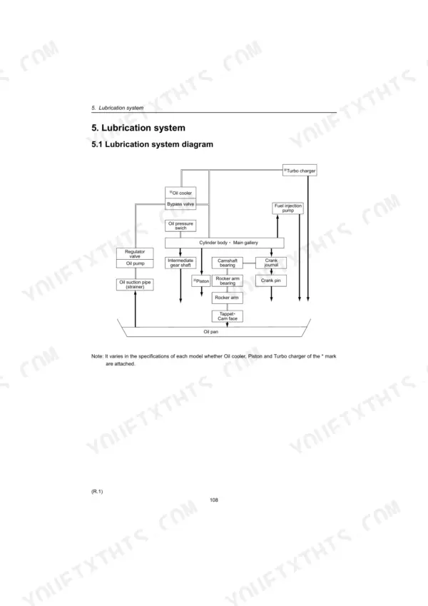
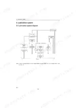
| Yanmar TNE94/98/106 Engine (Bundled Manual) | 312-491 | Engine Disassembly and Reassembly, Fuel Injection System, Cooling and Lubrication, Inspection and Adjustment, Engine Specifications |
| Yanmar Tnv / 4TNV Series Engine (Bundled Manual) | 492-711 | Engine Overhaul, Fuel System, Cooling and Lubrication, Electrical Equipment, Service Data and Torque |
Quick Reference Specifications
| Specification | Value | Page |
|---|---|---|
| Hydraulic Hoses Torque - Union Nut (G) - 1/8 | 9.8 +4.9/-0 N·m | p. 19 |
| Hydraulic Hoses Torque - Union Nut (G) - 1/4 | 24.5 +4.9/-0 N·m | p. 19 |
| Track Roller A Shaft and Bearing Bore Diameter Clearance Allowable Value | 0.095~0.16 mm | p. 32 |
| Idler Shaft and Bearing Bore Diameter Clearance Allowable Value | 0.08~0.18 mm | p. 35 |
| Bucket Cylinder & Lift Arm Standard Clearance | 0.07~0.20 mm | p. 37 |
| Bucket Cylinder & Quick Attachment Standard Clearance | 0.07~0.20 mm | p. 37 |
| Bolt: track roller A | 241 N·m | p. 67 |
| Bolt: track roller B | 156 N·m | p. 67 |
| Replace all seals | with new ones each time the hydraulic units is disassembled | p. 172 |
| Sealant for seal perimeter | Loctite #59231 | p. 185 |
| Hydraulic Hoses - Taper Thread (R) - 1/8 Hose Fitting Size (N·m) | 11.8 ±1.2 N·m | p. 19 |
Takeuchi TL130 Common Problems This Manual Covers
Takeuchi TL130 won't move after starting the engine and closing the lap belt
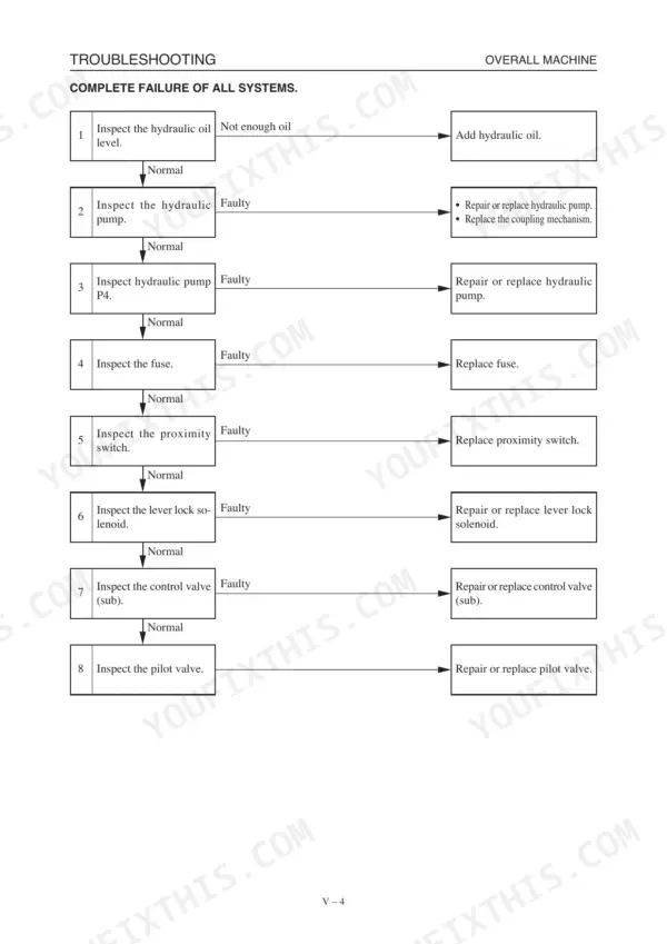
Check the troubleshooting chart on page 286 for complete failure of all systems. Verify hydraulic oil level against the 60 L total system capacity listed on page 31. Test the proximity switch and lever lock solenoid for continuity, then check the main fuse before you pull the control valve apart.
Manual Section: Overall Machine: Complete Failure of All Systems p. 286Complete loss of travel after the machine was parked overnight and restarted
Work through the travel train fault chart on pages 292-293. Gauge charge pressure and HST pump output pressure at the test ports, then inspect both high pressure relief valves for a stuck poppet. Idle run drag on the HST pump should hold at 8.5 N·m or less per page 185; anything higher points to a seized pump.
Manual Section: Machine Travel: Travel Train Fault p. 292All hydraulic systems work but deliver noticeably weak power under load
Follow the insufficient power troubleshooting on pages 289-290. Check hydraulic oil level, then listen for hydraulic pump noise while loaded. Remove and inspect the line filter for clogging, and check the control valve (sub) spool for binding. If you find a weeping fitting, torque 3/8 inch union nuts to 49 +4.9/-0 N·m per page 19.
Manual Section: Overall Machine: All Systems Working, but with Insufficient Power p. 289Lift arm cylinders won't move or respond when the joystick control is engaged
Reference the lift arm troubleshooting on pages 300-301. Verify actuator operation and pilot valve output first, then check spool movement in the control valve and test the port relief valves and arm float solenoid for proper switching. Bucket cylinder and lift arm clearance should read 0.07~0.20 mm per page 37; excess play there causes sluggish lift response.
Manual Section: Lift Arms: Lift Arm Cylinders Fail to Move p. 300Bucket cylinders move slowly or fail to curl under normal hydraulic pressure
Check the bucket cylinder troubleshooting on pages 306-307. Confirm pilot valve actuation and spool movement at the control valve, then test the port relief valves for correct cracking pressure. Measure cylinder leakage at the rod; anything over 1 cm³/3min exceeds spec per page 262 and calls for a reseal with new O-rings per page 250.
Manual Section: Bucket: Bucket Cylinders Fail to Move p. 306Track rollers grind and wear unevenly after heavy use on rocky ground
Pull the rollers and measure shaft-to-bearing bore clearance; allowable value is 0.095~0.16 mm per page 32. Check the idler shaft and bearing bore clearance too, spec is 0.08~0.18 mm per page 35. Torque the track roller A mounting bolt to 241 N·m and roller B to 156 N·m per page 67 before you put the machine back to work.
Manual Section: Ii . Specifications: Servicing Standards p. 32Frequently Asked Questions
What are the torque specifications for Takeuchi TL130 track roller bolts?
For Track Roller A, the installation bolts should be tightened to 241 N·m. For Track Roller B, the installation bolts should be tightened to 156 N·m. Thread-locking compound should be applied to these bolts. p. 67
What are the torque specifications for Takeuchi TL130 engine mounting bolts?
For serial numbers 21300004~21301932, the engine mount bolts require specific torques: A is 256 N·m, B is 97 N·m, and C is 55 N·m, all with thread-locking compound. For serial numbers 21301933~, A is 256 N·m, B is 116 N·m, C is 66 N·m, D is 5.9 N·m, and E is 3.9 N·m, also with thread-locking compound for A, B, and C. p. 47
How do you bleed air from the Takeuchi TL130 hydraulic system after a hydraulic fault or maintenance?
After replacing hydraulic oil or devices, bleed air from the hydraulic circuit. For the hydraulic pump, tilt up the canopy, remove plug (1), and reconnect it once hydraulic oil overflows. For cylinders, start the engine at low idle for 10 minutes, then extend and contract all cylinders 4 or 5 times without reaching stroke end. Repeat this at high speed, then at low idle to the stroke ends. p. 104
What is the hydraulic oil capacity for the Takeuchi TL130 hydraulic tank?
The hydraulic tank has a level capacity of 39 L. This information is found in the procedure for removing the hydraulic tank, specifically when draining the oil. p. 103
How will I receive this Takeuchi TL130 & variants Workshop Manual?
Immediate download of the complete 711-page searchable Workshop Manual. Access it on any device, from a laptop at your desk to a phone in the field.
Can I print this Takeuchi TL130 & variants manual?
Yes. Many mechanics print the section they need for their own shop and bring it to the bench.
Are hydraulic system diagrams in this Takeuchi TL130 & variants Workshop Manual?
Yes, complete hydraulic schematics with flow diagrams, valve configurations, and pressure specifications are included.
Reviews
There are no reviews yet.